- Cart
- |
- Personal Center
- |
info@idealphotonics.com

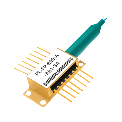



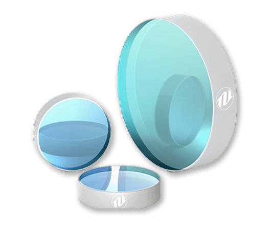
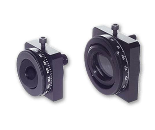
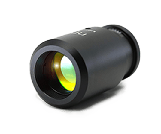
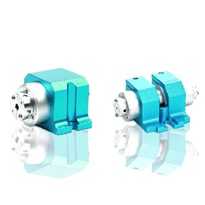


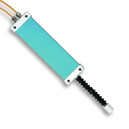
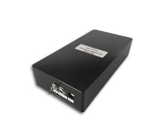









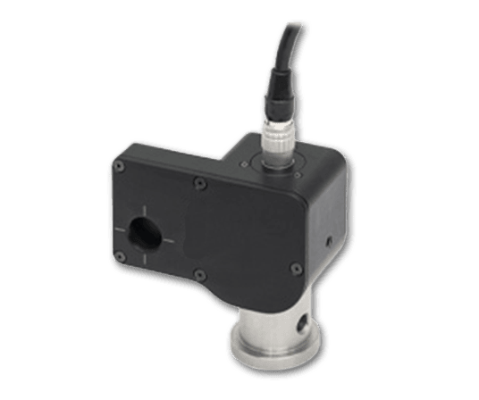

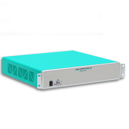
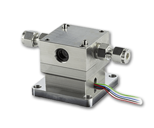
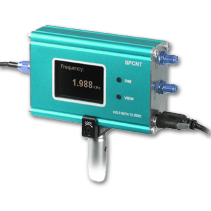


TO-Packaged Laser Diode Driver Module
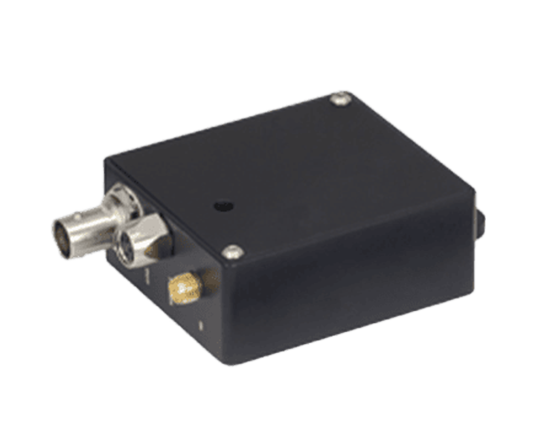
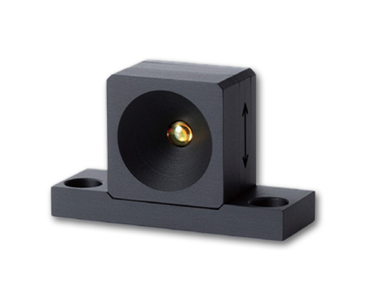
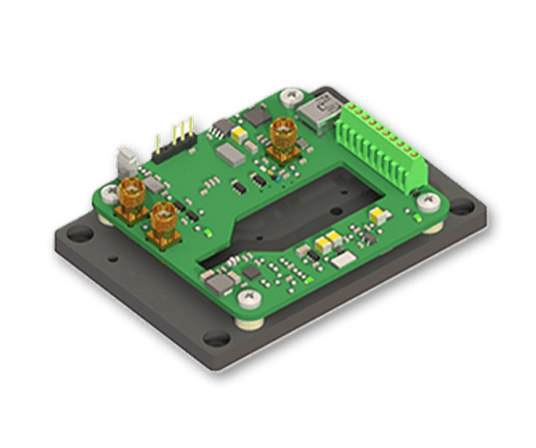
The TO-packaged laser diode driver module is a highly stable drive and temperature-control module for TO-packaged semiconductor laser diodes. It integrates constant-current drive, TEC temperature control, analog signal input, and an adjustable free-space beam collimation structure. The module has a built-in low-noise reference source, supports 16-bit current control, and provides multiple maximum drive current configurations, making it compatible with semiconductor lasers and VCSEL devices of different power levels. The module supports storage of current and temperature parameters and can directly recall preset parameters via external trigger to operate the laser. It also supports TTL serial port and USB expansion control. It is suitable for high-stability laser light sources, precision optical experiments, and OEM system integration.
Product features:Ultra-low-noise drive;High-precision temperature control;Multiple current ranges selectable;Multiple control methods
Part Number:MP-LDRVMLN-TO
Application area:Semiconductor laser driving and testing | High-stability laser light sources | Spectral and optoelectronic experiments | OEM optoelectronic system integration
Add to Cart Request for Quotation Consult Favorite
Drive current range Drive response frequency
12–624 mA 0–25 MHz
Characteristic | Min | Max | Unit | Notes |
Compatible lens diameter | 2 | 12.7 | mm | |
Power supply voltage | 4.8 | 6.0 | VDC | DC; regulated power supply recommended |
Power | 10 | W | ||
Maximum drive current (current range) | 12 | 624 | mA | Selected by different modules and jumpers |
Current resolution (LSB) | Current range / 65536 | mA | ||
Current linearity | ±1 | LSB | ||
Current temperature drift | ±25 | ppm/℃ | ||
Current noise | 200 | pA/Hz1/2 | Internal reference source only | |
Laser drive voltage | 3.4 / 2.8 | V | 5 V supply, half-amplitude current / full-amplitude current | |
4.3 / 3.7 | V | 6 V supply, half-amplitude current / full-amplitude current | ||
Response frequency | 0 | 25 | MHz | -3 dB |
Temperature control range | -10 | 50 | ℃ | |
Temperature resolution | 0.001 | ℃ | ||
Temperature stability | 0.002 | ℃ | Case heat dissipation | |
TEC output current | -1.5 | 1.5 | A | |
TEC output voltage | -4.6 | +4.6 | V | |
Analog input | 0 | 2.5 | V |
Panel Wiring
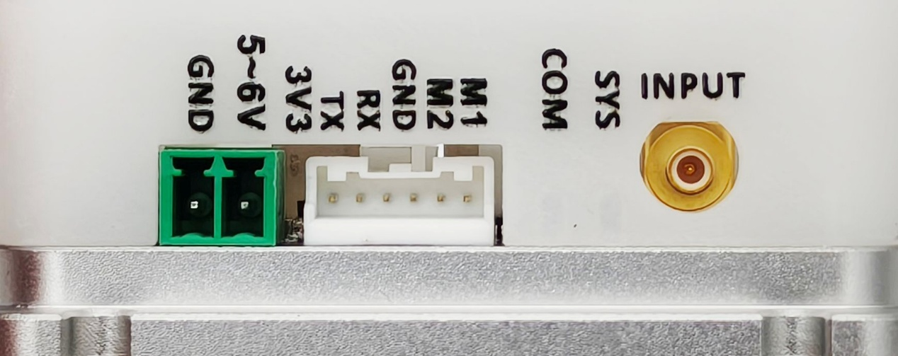
From left to right:
Power interface: 3.81 × 2P mm connector. Connector model: WJ15EDGRC-3.81-2P. DC 5–6 V, 3 A. Use a low-ripple regulated power supply to reduce overall system noise.
Communication interface: model S06B-PASK-2(LF)(SN)
1 | 2 | 3 | 4 | 5 | 6 |
3.3 V output For communication circuit power supply only | TX TTL-level transmit | RX TTL-level receive | GND Ground | M2 Auxiliary | M1 Auxiliary |
Serial communication: baud rate 115200 bps, 8 data bits, 1 stop bit, no parity; 3.3 V TTL level. A jumper can be used to short the GND and RX pins, causing the system to start driving the laser according to the configured internal current. Be sure to use this function only after all parameters are fully configured.
M1 and M2 are auxiliary connectors; the internal connectors can be used to directly connect to the laser pins.
COM LED: communication indicator. It lights red when GND and RX are shorted.
SYS LED: system status indicator. When no laser is installed or the laser temperature has not stabilized to the set value, it shows yellow. When the laser temperature is stable, it shows green. When the internal drive current is turned on, it shows red.
INPUT: SMB connector, connector model: 73100-0103. Input voltage 0–2.5 V, input frequency 0–20 MHz.
Internal Wiring
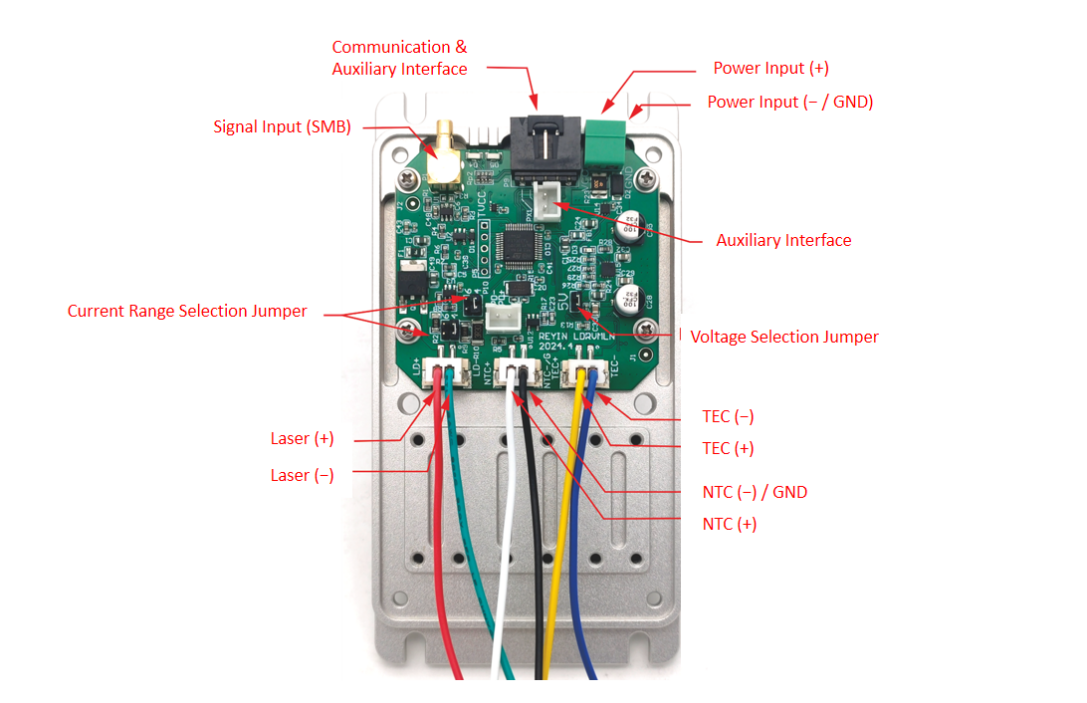
Be sure to first refer to the laser manual, the connector pinout, and the wiring on the circuit board to confirm that the laser is compatible with the current wiring sequence. Powering on with an incorrect wiring sequence may damage the laser!
The negative power input of the module, the baseplate, and the NTC negative terminal are all grounded. In addition, neither the positive nor the negative terminal of the drive output is grounded. Special attention is required when any functional pin of the laser to be installed is grounded (connected to its case).
When a laser functional pin is grounded (e.g., the laser positive terminal is grounded), a piece of adhesive thermal conductive silicone pad must be placed between the laser and the bottom case, and metal screws must not be used to fix the laser, so as to insulate the laser case from the bottom case. If unsure, please consult the seller's engineer. Incorrect grounding will cause abnormal module operation or even burn out the laser!
Notes
1. The driver is used in cases where the laser has a functional pin connected to the case (e.g., NEL lasers, whose positive terminal is often connected to the case). The laser case must be insulated from the base: place a layer of thermal conductive silicone pad under the laser, and do not use metal screws for fixing.
2. The drive positive terminal of the NEG-type laser driver is grounded and also connected to the chassis, so it can be used for lasers whose positive terminal is connected to the case.
3. The laser current range must be set via shorting caps (jumper caps) on P3 and P10. A mismatch between the two will cause the system's self-identification to not match the actual current, possibly burning out the laser!
4. It is recommended to first connect an LED or an inexpensive red laser to test whether the current settings work properly.
5. Laser temperature oscillation indicates that the temperature-control PID parameters are set incorrectly. The temperature-control parameter adjustment command is tecpkpkId. After sending, it takes effect immediately. Observe the temperature response accuracy and speed until satisfactory results are achieved. After adjustment, use the save command to save.
6. The module has no switch. After connecting power, the temperature control function starts working immediately, but the laser current source does not start. A green light indicates that the temperature is stable. Use a jumper cap to short RX and GND to make the current source start working. Please use this function only after the parameters are fully set!
7. Before power-on, the module's circuit parameters need to be adjusted to adapt to the installed laser. The parameters are controlled by jumpers and DIP switches on the circuit board. Be sure to operate with the power off!
8. Please set the maximum drive current equal to or slightly greater than the laser's maximum allowable current. If the drive current is set too large, it will increase the risk of burning out the laser.
Host Computer Control
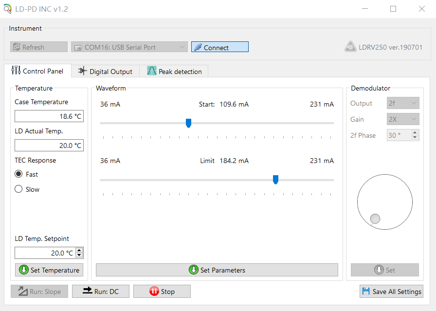
Find the corresponding virtual serial port in Communication Port. If it is not found, click the Refresh button. Click the Connect button. After a normal handshake, the console becomes active and reads the controller's current set values. Enter the required operating temperature in LD Temp Setpoint and click Set Temperature to set it. Use the Start slider to set the constant operating current value, and use the Limit slider to set the maximum current limit.
Click Set Parameters below to send the parameters to the instrument. Click Save All Settings to save all parameters in the instrument.
Click Run:DC to start the laser at the set current value. The Limit slider is used to protect the laser and can also limit the current under external input. Please set it to the maximum operating current in the laser parameter table.
--
Request for Quotation
We will reply to all your information about the product in time.
 10+
10 Years of Experience
 50
50 + Countries Bussiness
 10000
10k + Diodes sold worldwide
 30
30+ Invention patent
 10
10+ Advanced Optical Solutions
⇪