- Cart
- |
- Personal Center
- |
info@idealphotonics.com


RF Laser Diodes MINI Driver module LDRVMLN Instruction
LDRVMLN is a current drive and temperature control module for butterfly semiconductor laser diodes. Its main functions include: controlling the internal temperature of the laser, generating a constant current signal to drive the laser, and converting the external input voltage signal into a current drive. The module has three maximum current drive ranges, suitable for lasers of different power sizes (selected by circuit board jumpers). The built-in reference source has an extremely low noise level and can achieve 16-bit control accuracy. Current and temperature parameters can be stored on the module, and the laser can be operated with these parameters via a simple external trigger signal. This makes the module a plug-and-play, ultra-high stability laser light source.
Product features:RF modulation; Ultra low noise; Linear steady current; Mini compact; isolation protection
Part Number:MP-LDR-CW-MINI-RF
Application area:Fiber optic communication | Laser sensing | Precision machining | Scientific research experiments | Medical equipment
Add to Cart Request for Quotation Consult Favorite
Maximum Drive Current Temperature Control Range
149/378/624 mA -10~50℃
Features | Min | Max | Unit | Note |
Power voltage | 4.8 | 6.1 | VDC | DC It is recommended to use a regulated power supply |
Power | 10 | W | ||
Maximum drive current | 149/ 378/ 624 | mA | Jumper selection | |
Current resolution (LSB) | Max Current/65536 | mA | ||
Current linearity | ±1 | LSB | ||
Current temperature drift | ±25 | ppm/℃ | ||
Current noise | 200 | pA/Hz1/2 | Only built-in reference source | |
Laser drive voltage | 3.4/2.8 | V | 5V power supply Half amplitude current/full amplitude current | |
4.3/3.7 | V | 6V power supply Half amplitude current/full amplitude current | ||
Response frequency | 0 | 25 | MHz | -3db |
Temperature control range | -10 | 50 | oC | |
Temperature resolution | 0.001 | oC | ||
Temperature stability | 0.002 | oC | Requires enclosure cooling | |
TEC output current | -1.5 | 1.5 | A | |
TEC output voltage | -4.6 | +4.6 | V | |
Analog input | 0 | 2.5 | V |
Installation

Please be sure to refer to the laser manual, the wiring sequence of the corresponding connector, and the wiring on the circuit board to confirm that the laser is compatible with the current wiring sequence. Powering on with an incorrect wiring sequence may cause damage to the laser!
The negative input of the module's power supply, the bottom plate and the negative pole of the NTC are all grounded. The positive and negative poles of the drive output are not grounded. When any functional pin of the laser to be installed is grounded (connected to its shell), special attention should be paid.
When the laser function pin is grounded (such as the laser positive pole is grounded), a piece of sticky thermal conductive silicone needs to be placed between the laser and the bottom shell, and metal screws should not be used to fix the laser to insulate the laser housing from the bottom shell. If you are not sure, please consult the sales engineer. Improper grounding will cause module malfunction or even burn the laser!
Jumper Configuration
Before powering on, the module needs to adjust the circuit parameters to suit the installed laser. The parameters are controlled by jumpers and dip switches on the circuit board. Be sure to operate with power off!Please set the maximum drive current of LDRVMLN to be equal to or slightly larger than the maximum allowable current of the laser. If the drive current is set too high, the risk of burning out the laser will increase. Set the jumpers P3 and P10 on the circuit board:
Current selection jumper status | Instrument model/maximum drive current |
| LDRVMLN150 149mA |
| LDRVMLN380 378mA |
| LDRVMLN600 624mA |
| LDRVMLN400 394mA |
The jumpers P3 and P10 must be consistent, otherwise the instrument will not work properly! All operations should be performed with the power off.
Voltage selection jumper | ||
Input voltage | 5V | Maximum drive operating voltage |
5V | closure | 2.8V |
6V | disconnect | 3.7V |
If the laser has a built-in voltage divider resistor, try not to use it, as it will cause the external drive voltage to be insufficient and the laser will be in an undervoltage state.
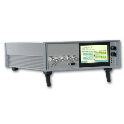
Panel

From left to right:
Power interface: 3.81mm connector, DC 5~6V, 3A. Use low ripple regulated power supply to reduce overall system noise.
Communication interface: serial communication, baud rate 115200bps, 8 data bits, 1 stop bit, no parity bit; 3.3V TTL level. You can use a jumper to short the GND and RX pins so that the system starts driving the laser according to the set internal current. Please be sure to use this function after all parameters are fully set.
P+, P- are auxiliary connectors, and the internal connector can be used to directly connect the laser pins.
COM light: communication indicator light, red light is displayed when GND and RX are shorted
SYS light: system status light. When the laser is not installed or the laser temperature is not stable to the set value, the yellow light is displayed. When the laser temperature is stable, the green light is displayed. When the internal drive current is turned on, the red light is displayed.
INPUT: SMB connector, input voltage 0~2.5V, input frequency 0~20MHz.
Pay attention!!
When the laser has a functional pin connected to the shell (such as NEL laser, the positive pole is often connected to the shell), the laser shell must be insulated from the base: a layer of thermal conductive silicone pad is placed under the laser, and do not use metal screws to fix it.
The laser current setting needs to be realized through short-circuit caps (jumper caps) at P3 and P10. Mismatch between the two will cause the system's self-identification and actual current to mismatch, which may cause the laser to burn out!
It is recommended to connect an LED lamp bead or a cheap red laser first to test whether the current setup is working properly.
Laser temperature oscillation indicates that the temperature control PID parameter settings are incorrect. The temperature control parameter adjustment command is tecp kp kI kd. It will take effect immediately after sending. Observe the temperature response accuracy and speed until a satisfactory effect is achieved. After the adjustment is completed, use the save command to save.
The module has no switch. After connecting the power supply, the temperature control function starts working immediately, but the laser current source does not start. The green light indicates that the temperature has stabilized. Use a jumper cap to short RX and GND to start the current source. Please use this function after the parameters are fully set!
External signal input
The signal input terminal INPUT on the rear panel of the instrument is used to receive external input. When the internal bias signal is not turned on, the equivalent circuit is shown in the figure below:

The driving current of the laser is:
ILaser = (V1/1.25V) x Imax
Imax=149mA , 378mA etc
When the internal signal is turned on, the equivalent circuit is as follows:

If you only use internal signals, disconnect all connections on the INPUT interface. If you want to use both internal and external signals, please calculate the final effect yourself according to the above equivalent circuit.
PC Control Interface
Replace the instrument cover, connect the controller to the power supply, and connect it to the computer with a USB cable. WIN7 and above systems will prompt to automatically connect to the Internet to install the USB driver. When using other systems or unable to connect to the Internet, please download the corresponding driver at http://www.ftdichip.com/Drivers/VCP.htm. After the driver is installed, a virtual serial device will appear in the "Device Manager".
Open the dedicated software on the computer, as shown below:

Find the corresponding virtual serial port in Communication Port. If not found, click the Refresh button. Click the Connect button. After a normal handshake, the console lights up and reads the current setting value of the controller. Enter the required operating temperature in LD Temp Setpoint and click Set Temperature to set it. The Start slider sets the constant operating current value, and the Limit slider sets the maximum limit current. Click Set Parameters below to send the parameters to the instrument. Click Save All Settings to save all parameters in the instrument.
Click Run:DC to start the laser with the set current value. The Limit slider is used to protect the laser and can also limit the current under external input conditions. Please set it to the maximum operating current in the laser parameter table.
Before starting the laser, please carefully check whether each parameter is within the allowable operating range of the laser!
Communication Instructions
The dedicated conversion cable connects the circuit board to the computer USB or serial port. The USB converter uses the FT232R chip to simulate the serial port. WIN7 and above systems will automatically connect to the network and install the driver. For other systems or when not connected to the network, please download the corresponding driver at http://www.ftdichip.com/Drivers/VCP.htm. After the driver is installed, a new serial device will appear in the "Device Manager". The communication rate defaults to 115200bps. Change the parameters by receiving ASCII format serial commands, and the command ends with a carriage return.
The following uses PuTTY as an example to explain the communication method. After opening PuTTY, select Serial for connection, enter the port number that is consistent with the device manager, enter 115200 in Speed, click open to open the black interactive port, and enter the relevant commands through the keyboard (the Backspace key is invalid). After entering the command correctly, the system will prompt the setting result, and an error message will be returned if an error occurs.

The computer is the main control terminal (host computer) and sends a string command. A line of command starts with a colon ":" and ends with a carriage return (\r\n). The lower computer returns information after execution. All the following functions can be accessed through the supporting software. It is recommended to complete the settings with the supporting LDPD software and get the correct waveform, then click Save to save the parameters to the lower computer, and then transfer it to other clients for control.
The operation modes are as follows:
1 | operation mode |
>>>>>> Send auto on start, return (1) Auto run started. [[OK]]\r\n >>>>>> Send auto off to stop, return (0) Auto run stopped. [[OK]]\r\n
|
Parameter settings:
Send | Function and return value |
about | Returns the current parameters of the lower computer: >> First line (%f) TEC.\r\n >> (Floating point number, consistent with the parameters sent) >> The second line (%d,%d,%d) PGA,freq,amp.\r\n >> (For the LDRV module, the above parameters are meaningless) >> The third line (%d,%d,%d) bias.\r\n >> (The value is consistent with the bias a, b, c issued by the command) >> Line 4 (%d,%d) dm,phase.\r\n >> (LDRV is a meaningless parameter) |
version | Reply: RYMLASER |
temp | Returns the current ambient temperature, laser temperature, and readback current value |
tec x | X is Celsius temperature, sets the target temperature of the laser, which can be a decimal. |
tecp kP kI kD | Sets the PID parameters of the temperature control system to ensure the stability of the temperature control system. Users can adjust the parameters to achieve fast or slow response For professional users only! Poor PID parameters can cause temperature oscillations and even damage the laser System factory values: kP = 1500; kI = 4000; kD = 10 |
tecfast | TEC normal mode, using stored PID parameters |
tecslow | TEC slow mode, kP/2, kI/8, will reduce the time |
bias a b c | a: Current setting(0~65535) b: Current limit setting(0~65535) c: Meaningless parameter, set to a value above 1 The values of a and b are calculated using the following formula a = (Iset/Imax)*65536 Iset is the current to be set, and Imax is the maximum current of the instrument (based on the model of the machine, check in Instruments.ini) |
save | Save all current parameters and they will be automatically called next time the computer is turned on. |
--
Request for Quotation
We will reply to all your information about the product in time.
⇪