- Cart
- |
- Personal Center
- |
info@idealphotonics.com


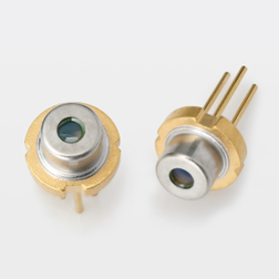
1064nm 300mW 50ps SM Pulsed DFB Laser Diode
This product offers a broad portfolio of high-power single-spatial-mode laser diodes, suitable for any wavelength within the 780nm to 1340nm range. It is available with a TO-9 (9mm) free-space light output package or a standard 14-pin butterfly package with fiber pigtail output (both single-mode and polarization-maintaining pigtails are optional). The polarization extinction ratio (PER) of laser diodes with polarization-maintaining (PM) pigtail output is typically >18dB. These fiber-coupled laser diodes can be configured for CW (up to 600mW) or pulsed operation, and are optionally available with fiber Bragg grating (FBG) versions for spectral stabilization. The pulsed laser diodes from Idealphotonics are specifically designed for seed source applications, featuring low-noise peak optical power up to 1.2W, and a broadened spectrum that suppresses stimulated Brillouin scattering (SBS) in high-power fiber lasers. Each laser diode product line undergoes a qualification program to demonstrate high reliability. All provided lasers pass individual screening procedures and are accompanied by detailed factory test reports.
Product features:High peak power;Single-longitudinal-mode narrow linewidth;Fast response;Low thermal effect;Industrial-grade packaging
Part Number:MP-DFB-PL-1064-300-14BF-SA
Application area:Laser ranging | Distributed fiber-optic acoustic sensing | Optical coherence tomography | Industrial processing | Laser-induced breakdown spectroscopy
Add to Cart Request for Quotation Consult Favorite
Peak Wavelength Output Power Pulse Duration (Width) Fiber Type
1027-1080 nm 300 mW 50 ps HI-1060
Specifications
Test operating conditions | |||||
Parameters | symbol | Min. | Typ. | Max. | unit |
Pulse current amplitude | Iamp | 600 | mA | ||
DC current (via Bias-T) | IDC | 3 | mA | ||
Pulse current duration (FWHM) | τel | 350 | ps | ||
Pulse repetition rate | F | 1 | 250 | MHz | |
Chip temperature | Top | 15 | 25 | 40 | ℃ |
Light pulse Test conditions: @operating point, Tcase=25°C. | |||||
Parameters | symbol | Min. | Typ. | Max. | unit |
Peak power | Ppeak | 250 | 300 | mW | |
Pulse duration (FWHM). | τ | 50 | 60 | ps | |
Center wavelength | λ | 1028 | 1080 | nm | |
Wavelength tolerance | λt | 1 | nm | ||
Spectrum width (-10dB). | Δλ-10dB | 0.1 | 0.150 | 0.2 | nm |
Wavelength heat coefficient | Δλ/ΔT | 90 | 110 | pm/℃ | |
jue to Max. Rating | |||
Parameters | Min. | Max. | unit |
LD Forward Current (CW) | 250 | mA | |
LD forward current (pulse, 2% duty cycle) (Pulse, 2% duty cycle) | 2 | A | |
Laser diode reverse voltage | 1 | V | |
TEC current | 3 | A | |
TEC voltage | 4 | V | |
Storage temperature range (in original sealed packaging) | 5 | 80 | °C |
Wire soldering temperature (Max. 5 seconds). | 250 | °C | |
Enclosure operating temperature range | 10 | 50 | °C |
Product characteristics:
Typical performance is for reference only
Test conditions: @ operating point, Tcase=25°C
Pulse shape
RF module, pulse generator; Triggered by splitting light signals; 50ps/div

Laser spectroscopy
10pm resolution

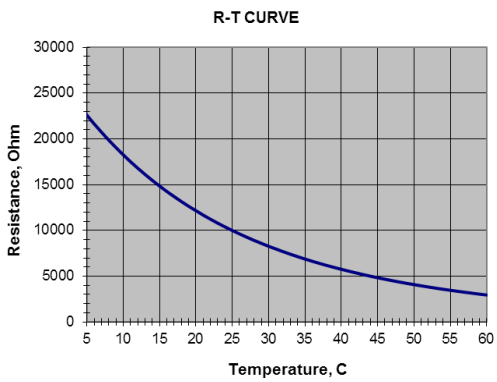
Thermistor specifications | Fiber Specifications | |||||
Parameters | value | unit | Parameters | HI1060 | PM980 | unit |
Thermistor type | NTC | Numerical aperture (Typical). | 0.14 | 0.12 | - | |
Impedance @ 25°C | 10 ± 0.1 | kOhm | Cut-off wavelength | 920±50 | 900±70 | nm |
Beta 0-50°C | 3375 | K | Mold field diameter (@1060nm). | 6.2±0.3 | 6.6±0.3 | μm |
| Cladding diameter | 125±1 | 125±1 | μm | ||
Offset from core layer to cladding Core-to-cladding offset | ≤0.5 | ≤0.5 | μm | |||
Fiber length | 1.0 ± 0.1 | 1.0 ± 0.1 | m | |||
connectors | FC/APC (Narrow Key) | |||||
Slow axis alignment | ||||||
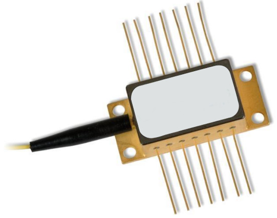
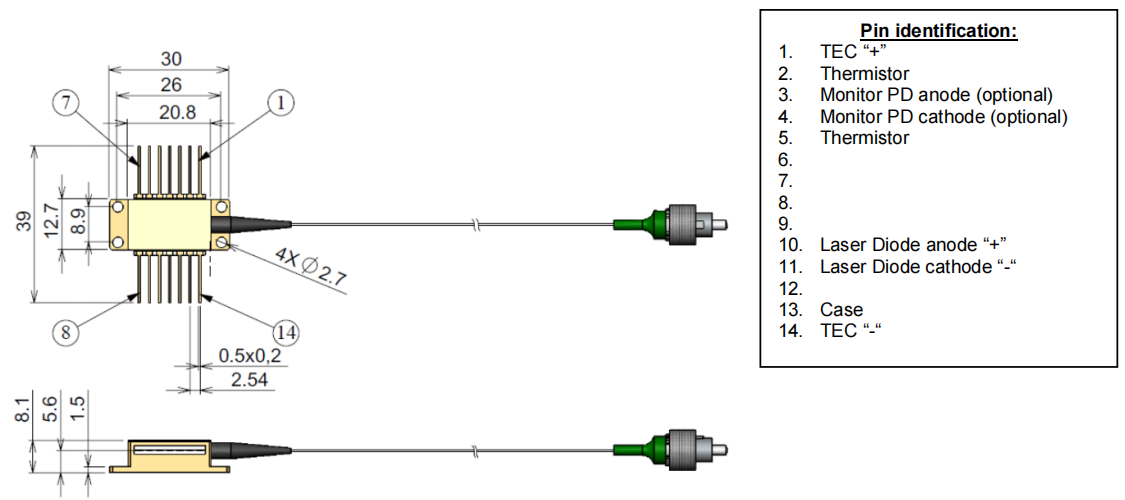
Dimensional drawings
14-pin diode size (all sizes are in mm).
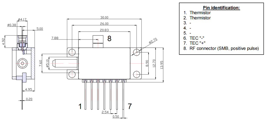
Dimensions with RF connectors (all dimensions are in mm).
Model parameters
Peak wavelength range 3 | Output pulse power 4 | Pulse duration | Spectral width 4 (-10dB). | Wavelength temperature adjustability | Operating current |
nm | mW | nm | pm/K | mA | |
1027 – 1080 | 300 | 50 ps | 0.150 | 90 | 600 |
1027 – 1080 | 300 | 60 ps | 0.150 | 90 | 600 |
1027 – 1080 | 300 | 1-10 ns | 0.150 | 90 | 1000 |
3 – Any wavelength in this range is available with a tolerance of ±1nm
4 – In Gain Switching Mode
5–Picosecond (gain switching) and nanosecond laser diode drivers can be ordered with the laser or separately
The light emitted by the device is invisible and may be harmful to the human eye. When the device is in operation, avoid looking directly at the fiber optic connector. When operating with the connector open, it is essential to wear appropriate laser safety glasses.
Absolute Max. ratings should only be applied to laser diodes for short periods of time. Prolonged exposure to Max. ratings or exposure to more than one Max. rating may cause damage to the device or affect its reliability. Operating a laser diode outside of the Max. rating may result in equipment failure or safety hazards
The power supply used with the part must be used to ensure that the Max. forward current is not exceeded
An appropriate heat sink needs to be provided for the laser diode on the heat sink. The laser diode must be mounted on the heat sink with 4 screws (tightened in an X-shaped manner, with an initial torque set to 0.075 Nm and a final X-bolt to 0.15 Nm) or a clamp. The deviation of the surface flatness of the radiator must be less than 0.05mm. It is recommended to use indium foil or thermally conductive soft material as a thermal interface between the bottom of the housing and the radiator. Hot grease is not desired
Avoid back reflections from laser diodes. It can have an impact on device performance in terms of spectrum and power stability. It can also lead to fatal laser diode end face damage. Optical isolators are highly recommended to block back reflections. Do not pull the fiber. Do not bend fibers with a radius of less than 3 cm.
Only the laser module can be operated with clean fiber optic connectors. If necessary, regularly inspect and clean the fittings. To clean the connector, only use a cleanroom-compatible paper towel, place some isopropyl alcohol on it and carefully clean the end face of the connector, or use a special fiber optic cleaning tool. Cleaning is carried out only with the laser current turned off.
Electrostatic discharge can cause equipment failure. Take the necessary precautions to prevent ESD.
--
Request for Quotation
We will reply to all your information about the product in time.
⇪