- Cart
- |
- Personal Center
- |
info@idealphotonics.com


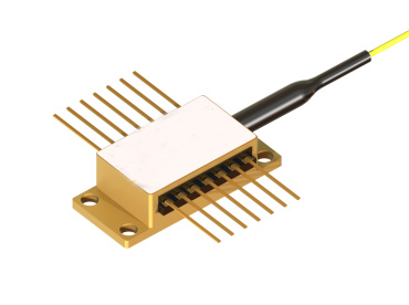
990nm 150mW PM Fiber-Coupled Laser Diode
The fiber-coupled laser diodes from idealphotonics feature a compact structure, easy integration and high stability. They also reduce optical loss during long-distance transmission, maintain beam quality, and meet the requirements of high-demanding applications.
Product features:High-efficiency fiber coupling;Multiple wavelengths available;Low-noise output;Compact and modular;Fast modulation
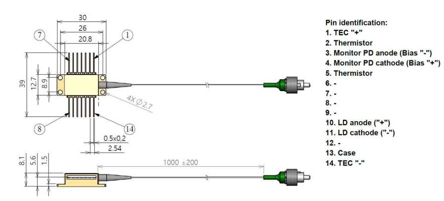
Part Number:MP-FP-990-150-14BF-PA
Application area:Fiber Optic Sensing | Medical Equipment | Industrial Processing | Optical Communication | Scientific Research Experiments
Add to Cart Request for Quotation Consult Favorite
Central Wavelength Output power
990nm 150mW
Product Parameters
Available Power Options | |||||
Condition: | CW operation, chip temperature 25°C, package mounted on room-temperature heat sink | ||||
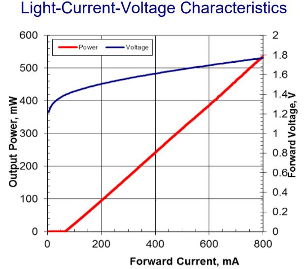
Part Number | Output Power (Pout), mW | Operating Current (mA) | Forward Voltage (V) | ||
Typ. | Max. | Typ. | Max. | ||
MP-FP-9XX-150 | 150 | 300 | 370 | 1.6 | 1.8 |
MP-FP-9XX-200 | 200 | 350 | 420 | 1.6 | 1.8 |
MP-FP-9XX-250 | 250 | 400 | 470 | 1.6 | 1.8 |
Specifications | |||||
Condition: | CW operation, chip temperature 25°C, package mounted on room-temperature heat sink | ||||
Parameter | Symb. | Min. | Typ. | Max. | Unit |
Un-twisted Output Power | - | 1.1×Pout | 1.3×Pout | - | mW |
Available Wavelength Range | λ | 900 | - | 1010 | nm |
Average Wavelength Tolerance | - | - | - | 5 | nm |
Spectral Bandwidth at -3dB level at Pout | Δλ | - | <0.5 | 4 | nm |
Threshold Current | Ith | - | 70 | 100 | mA |
Wavelength Temperature Tunability | Δλ/ΔT | 0.3 | - | 0.4 | nm/°C |
Polarization Extinction Ratio | PER | 12 | - | - | dB |
* ∆P/∆I > 0 (∆I=5mA)
Absolute Maximum Ratings | |||
Parameter | Min. | Max. | Unit |
Laser Diode Reverse Voltage | - | 2 | V |
Laser Diode CW Forward Current | - | Iop+300 | mA |
Thermoelectric Cooler Current | - | 3 | A |
Thermoelectric Cooler Voltage | - | 4 | V |
Fiber Bending Radius | 3 | - | cm |
Chip Operating Temperature Range | 5 | 40 | °C |
Package Operating Temperature Range | 0 | 70 | °C |
Storage Temperature Range | -40 | 85 | °C |
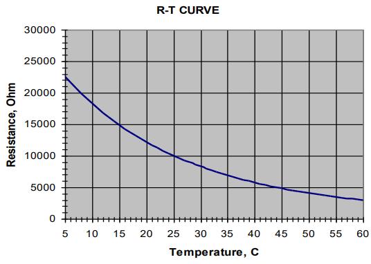
Thermistor Specifications | Fiber Optic Specifications | |||||
Parameter | Value | Unit | Parameter | HI1060 | PM980 | Unit |
Thermistor Type | NTC | Numerical Aperture (Typ.) | 0.14 | 0.12 | ||
Resistance @25°C | 10 ± 0.1 | kOhm | Cutoff Wavelength | 920±50 | 900±70 | nm |
Beta 0-50°C | 3375±1% | K | Mode Field Diameter (@1060nm) | 6.2±0.3 | 6.6±0.3 | μm |
| Cladding Diameter | 125±1 | 125±1 | μm | ||
Coating Diameter | 245±15 | 245±15 | μm | |||
Length | 1.0 ± 0.1 | 1.0 ± 0.1 | m | |||
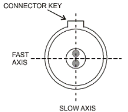
Connector | FC/APC (narrow key) | |||||
Align connector with PANDA fiber | ||||||
Output light is polarized along the slow axis of the PM fiber | ||||||
Typical performance curves for reference only
Photoelectric Current-Voltage Characteristics
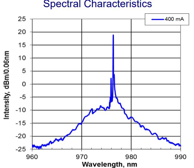
Spectrum - (Resolution 0.05nm)
The light emitted by this equipment is invisible and may be harmful to human eyes. When the equipment is running, avoid directly viewing the fiber connector. When operating with the connector open, appropriate laser safety goggles must be worn.Absolute maximum ratings can only be applied to the equipment for a short time. Long-term exposure to maximum ratings or exposure to more than one maximum rating may cause equipment damage or affect the reliability of the equipment. Operating the equipment outside the maximum ratings may lead to equipment failure or safety hazards. The power supply used with the component must be used to ensure that the maximum forward current is not exceeded.Equipment on the heat sink requires a suitable heat sink. The device must be mounted on the heat sink using 4 screws (tightened in an X-pattern, initial torque set to 0.075Nm, final X-pattern screw tightening to 0.15Nm) or fixtures. The flatness deviation of the heat sink surface must be less than 0.05mm. It is recommended to use indium foil or thermally conductive soft material as the thermal interface between the bottom of the housing and the heat sink. Thermally conductive grease is not recommended.Avoid back reflection from the equipment. It may affect the equipment performance in terms of spectral and power stability. It may also cause catastrophic damage to the facet. It is strongly recommended to use an optical isolator to block back reflection.Do not pull the fiber. Do not bend the fiber with a radius smaller than 3 cm. During installation, always protect the fiber end face from any contamination or damage. After removing the dust cap covering the fiber end face, gently wipe isopropyl alcohol or ethanol with an optical lens cleaning tissue or cotton swab, and carefully clean the fiber end face in one direction. Operate the equipment only with clean fiber connectors.Electrostatic discharge is the main cause of unexpected product failure. Take extreme preventive measures to prevent ESD. During equipment installation, ESD protection must be maintained — use wrist straps, grounded work surfaces and strict
--
Request for Quotation
We will reply to all your information about the product in time.
⇪