- Cart
- |
- Personal Center
- |
info@idealphotonics.com

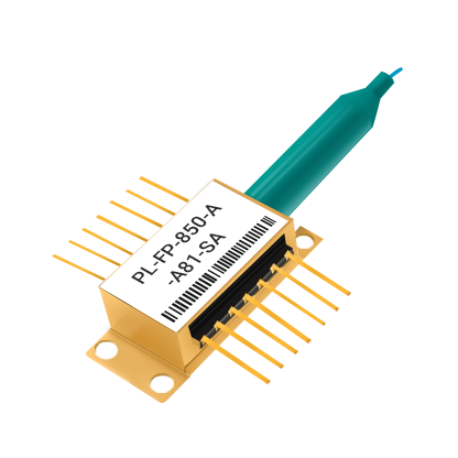

















1×N Series Asymmetric Multimode Optical Splitter
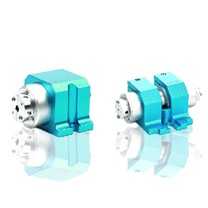
The 1×N series asymmetric multimode optical splitter adopts PLC planar lightwave circuit technology and is manufactured using a glass-based ion-exchange process. It can realize non-uniform power distribution of optical signals according to different splitting ratios. The product features low insertion loss, low polarization-dependent loss, high directivity, and a wide operating wavelength range, and can meet the differentiated optical power distribution requirements of different multimode fiber systems. This series offers various splitting ratios such as 5/95, 10/90, 20/80, 30/70, 40/60, and multi-channel non-uniform splitting. It supports customization of fiber type, connectors, and packaging methods, and is suitable for fields such as optical fiber communications, industrial control, optical inspection, and optical fiber sensing.
Product features:Flexible splitting with multiple ratios;Low loss, high directivity;Wide wavelength, high compatibility;Miniaturized, customizable
Part Number:MP-1×N-AM-MOS
Application area:Optical fiber communication systems | Industrial control and monitoring | Optical fiber sensing systems | Optical testing and measurement
Add to Cart Request for Quotation Consult Favorite
Operating Wavelength Polarization-Dependent Loss
650–1350 nm ≤0.1 dB
Dual-channel Asymmetric Splitting Specifications
Splitting ratio | 5/95 | 10/90 | 20/80 | 30/70 | 40/60 |
Operating wavelength (nm) | 650–1350 | 650–1350 | 650–1350 | 650–1350 | 650–1350 |
Typical insertion loss (dB) | 13.7/0.9 | 10.7/1.1 | 7.7/1.6 | 6.0/2.2 | 4.8/2.9 |
Maximum insertion loss (dB) | 14.0/1.1 | 11.0/1.2 | 8.0/1.7 | 6.3/2.4 | 5.0/3.0 |
Polarization-dependent loss (dB) | ≤0.1 | ≤0.1 | ≤0.1 | ≤0.1 | ≤0.1 |
Chip size (mm) | 2.2×1.8×16.4 | 2.2×1.8×10.4 | 2.2×1.8×10.4 | 2.2×1.8×13.4 | 2.2×1.8×16.4 |
Multi-channel Asymmetric Splitting Specifications
Splitting ratio | Typical insertion loss (dB) | Maximum insertion loss (dB) |
10/20/70 | 12.1/8.0/3.0 | 12.1/8.2/3.2 |
10/10/10/70 | 11.4/11.4/11.4/3.0 | 11.6/11.6/11.6/3.2 |
10/10/80 | 11.0/11.0/1.6 | 11.2/11.2/1.7 |
40/40/20 | 4.7/4.7/7.9 | 4.8/4.8/8.1 |
15/15/70 | 9.1/9.1/2.2 | 9.4/9.4/2.4 |
General Technical Parameters
Parameter | Technical specification |
Operating wavelength | 650–1350 nm, or customized on demand |
Polarization-dependent loss | ≤0.1 dB |
Return loss | ≥40 dB, or customized on demand |
Directivity | ≥50 dB |
Fiber type | 50/125 or 62.5/125 μm multimode fiber |
Loose tube specification | 900 μm |
Connector type | Customized on demand |
Pigtail length | ≤1.5 m, or customized on demand |
Chip channel spacing | 250 μm |
Chip and Package Dimension Parameters
Splitting ratio | Chip size (mm) | Bare-fiber micro-sealed steel tube size (mm) | Sleeve micro-sealed steel tube size (mm) |
5/95 | 2.2×1.8×16.4 | 4×7×50 | 4×7×55 |
10/90 | 2.2×1.8×10.4 | 4×7×50 | 4×7×55 |
20/80 | 2.2×1.8×10.4 | 4×4×40 | 4×7×50 |
30/70 | 2.2×1.8×13.4 | 4×4×40 | 4×7×50 |
40/60 | 2.2×1.8×16.4 | 4×7×50 | 4×7×55 |
10/20/70 | 2.2×1.8×19.4 | 4×7×55 | 4×7×60 |
10/10/10/70 | 2.2×1.8×21.9 | 4×7×60 | 4×7×60 |
10/10/80 | 2.2×1.8×20.4 | 4×7×55 | 4×7×60 |
40/40/20 | 2.2×1.8×18.9 | 4×7×55 | 4×7×55 |
15/15/70 | 2.2×1.8×16.4 | 4×7×50 | 4×7×55 |
--
Request for Quotation
We will reply to all your information about the product in time.
 10+
10 Years of Experience
 50
50 + Countries Bussiness
 10000
10k + Diodes sold worldwide
 30
30+ Invention patent
 10
10+ Advanced Optical Solutions
⇪