- Cart
- |
- Personal Center
- |
info@idealphotonics.com

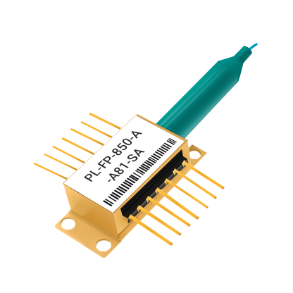

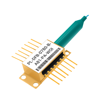
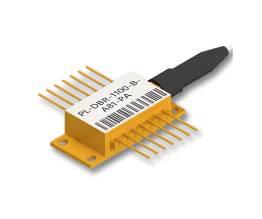
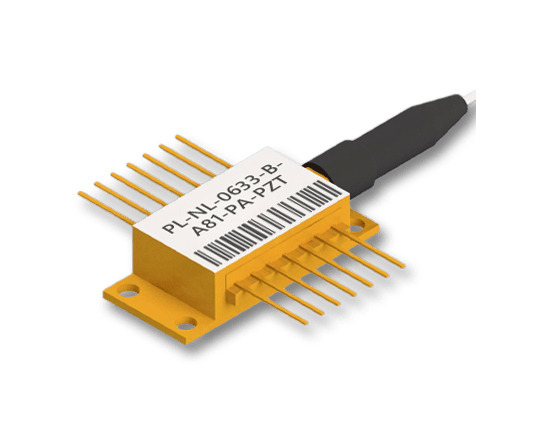
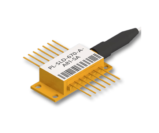


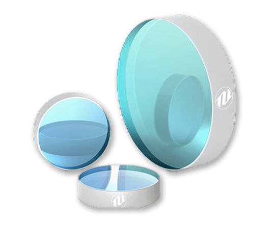
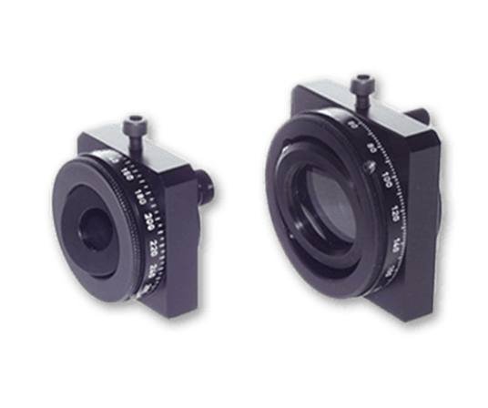
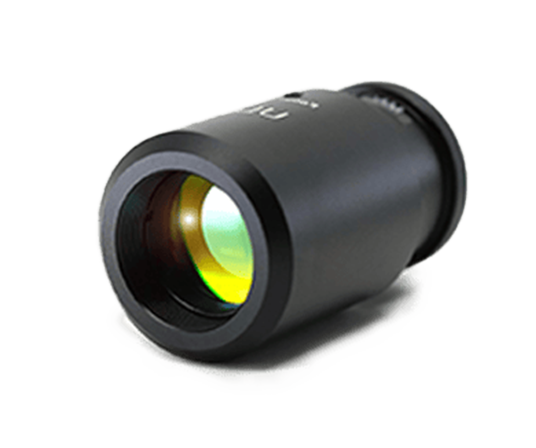
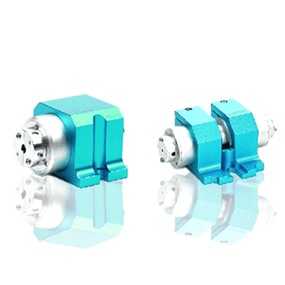


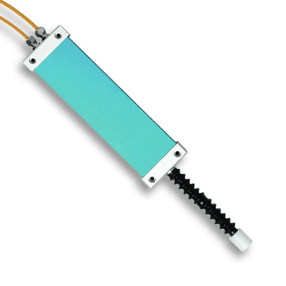









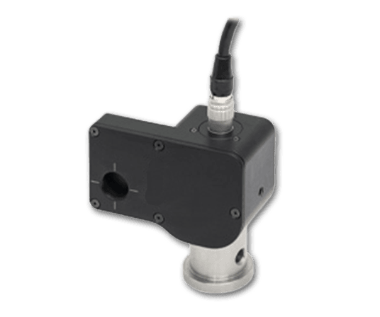



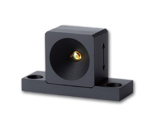
1D Adjustable Fiber Collimator
The 1D adjustable fiber collimator is a key passive optical component in fiber optic signal chains, primarily used to convert the divergent beam emitted from an optical fiber into a high-quality collimated parallel beam. It is widely applied in laser systems, fiber optic communications, spectral analysis, research experiments, and precision optical testing.The product features an FC/APC fiber interface, is compatible with single-mode fiber patch cords, and offers three AR coating wavelength bands: 400-700 nm, 600-1050 nm, and 1050-1700 nm, meeting the needs of various wavelength applications.
Product features:Wide wavelength compatibility, covering ultraviolet to near-infrared; Pure axial focusing without rotational offset; Fully mechanical locking, temperature and humidity stability; Made of silicon brass material, with micrometer level precision.
Part Number:MP-FCA-4.4-400-700
Application area:Fiber laser systems | Laser collimation | Spectral analyzers | Fiber optic communications | Biomedical optical detection | Research laboratory platforms
Add to Cart Request for Quotation Consult Favorite
Operating Wavelength Effective Focal Length (EFL) Numerical Aperture (NA)
350–700 nm/600–1050 nm/1050–1700 nm 4.4 mm/7.35 mm/10.7 mm /17.9 mm 0.54/0.30/0.15
Wavelength | EFL | Fiber MFD | Waist Beam Diameter | NA (Lens) | AR Coating | Transmittance |
400~700 nm | 4.4 mm±10% | 3.5 μm | 0.86 mm±10% | 0.54 | R<0.5%@400~700 nm | >92% |
600~1050 nm | 4.5 mm±10% | 5 μm | 0.98 mm±10% | 0.54 | R<0.5%@600~1050 nm | >92% |
1050~1700 nm | 4.56 mm±10% | 10.4 μm | 0.87 mm±10% | 0.54 | R<0.5%@1050~1700 nm | >92% |
400~700 nm | 7.35 mm±10% | 3.5 μm | 1.35 mm±10% | 0.3 | R<0.5%@400~700 nm | >92% |
600~1050 nm | 7.5 mm±10% | 5 μm | 1.6 mm±10% | 0.3 | R<0.5%@600~1050 nm | >92% |
1050~1700 nm | 7.6 mm±10% | 10.4 μm | 1.44 mm±10% | 0.3 | R<0.5%@1050~1700 nm | >92% |
400~700 nm | 10.7 mm±10% | 3.5 μm | 1.96 mm±10% | 0.3 | R<0.5%@400~700 nm | >92% |
600~1050 nm | 11.0 mm±10% | 5 μm | 2.35 mm±10% | 0.3 | R<0.5%@600~1050 nm | >92% |
1050~1700 nm | 11.2 mm±10% | 10.4 μm | 2.1 mm±10% | 0.3 | R<0.5%@1050~1700 nm | >92% |
400~700 nm | 17.9 mm±10% | 3.5 μm | 3.2 mm±10% | 0.15 | R<0.5%@400~700 nm | >92% |
600~1050 nm | 18.4 mm±10% | 5 μm | 4.0 mm±10% | 0.15 | R<0.5%@600~1050 nm | >92% |
1050~1700 nm | 18.6 mm±10% | 10.4 μm | 3.5 mm±10% | 0.15 | R<0.5%@1050~1700 nm | >92% |
Adjustment Procedure
1. Loosen the locking screws;
2. Rotate the eccentric lever to adjust the beam spot to the desired size;
3. Tighten the two locking screws alternately to complete the lock.

Thermal Stability Test
After 24 hours of continuous testing, the coupling efficiency decreased by 1.85 percentage points. The temperature curve shows that the ambient temperature fluctuated between 21 °C and 27 °C, while the collimator temperature and the optical table temperature remained largely synchronized, with no significant thermal drift.
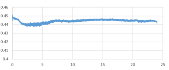
Coupling Power Thermal Stability Curve
X-axis:Time(h) Y-axis:Coupling Power (mW)
Beam Spot Stability Test (Test Sample EFL 11 mm)
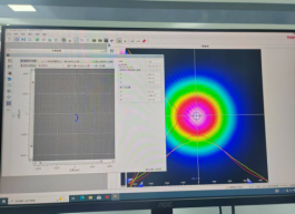
The eccentric lever was rotated one full turn in the adjustment hole, and the displacement trajectory of the beam intensity centroid was recorded. The figures below show the test results for our product compared with those of a competitor (Company K).
In the beam spot stability test, the beam centroid displacement trajectory of our product is comparable to that of Company K’s product, meeting the requirements for high‑precision fiber coupling/collimation applications.
Microphotons
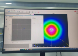
Company K’s product
--
Request for Quotation
We will reply to all your information about the product in time.
 10+
10 Years of Experience
 50
50 + Countries Bussiness
 10000
10k + Diodes sold worldwide
 30
30+ Invention patent
 10
10+ Advanced Optical Solutions
⇪