- Cart
- |
- Personal Center
- |
info@idealphotonics.com






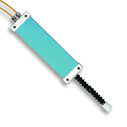
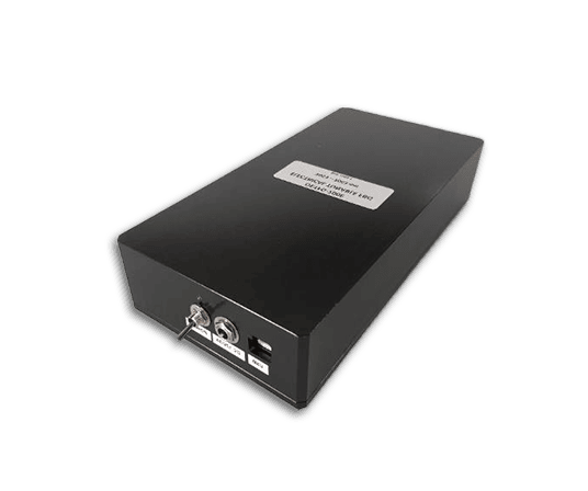


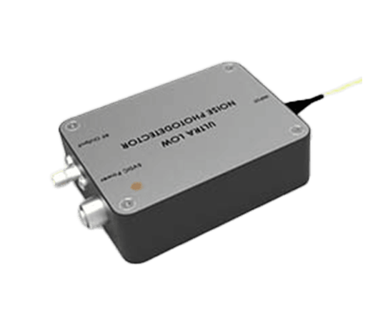
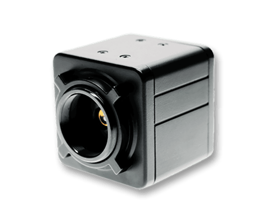









FPV Drone Fiber Optic System
The drone fiber optic transmission system is a fiber optic communication system specifically developed for UAV applications. The system transmits analog video signals, high‑definition video signals, and TTL level signals over optical fiber, and can be expanded to include RS485, RS422, RS232 asynchronous data, bidirectional audio, telephone, and dry contact signals as required. It is suitable for long‑distance, low‑interference, high‑stability UAV communication scenarios.
Product features:Fiber optic transmission with strong immunity to electromagnetic interference;Supports video signal and data/control signal transmission;Supports PAL/NTSC video protocols;Supports CRSF, PPM, SBUS and other control protocols;Single‑fiber FC optical connector; Airborne unit is compact and lightweight, ideal for UAV mounting
Part Number:MP-FPV-5
Application area:Emergency Rescue | Power Line Inspection | Oil & Gas | Transportation Inspection | Forest Fire Prevention | Maritime Inspection | Geological Surveying & Mapping | R&D & Testing
Add to Cart Request for Quotation Consult Favorite
Length Optical Connector
5-60 km FC/UPC
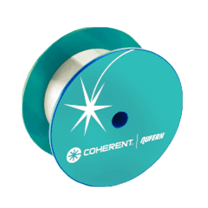
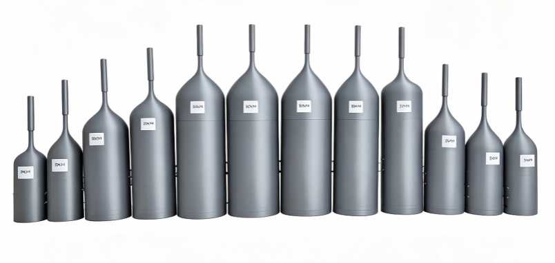
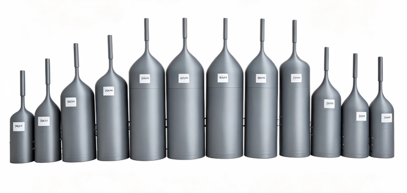
Fiber Payoff Reel Specifications
Length | Fiber Model | Housing Material | Optical Connector | Product Dimensions | Product Weight |
5KM | MP-FPV-5 | ABS | FC/UPC | 10×10×28CM | 600g |
10KM | MP-FPV-10 | ABS | FC/UPC | 12×12×37CM | 1180g |
15KM | MP-FPV-15 | ABS | FC/UPC | 12×12×37CM | 1600g |
20KM | MP-FPV-20 | ABS | FC/UPC | 12×12×37CM | 1960g |
25KM | MP-FPV-25 | ABS | FC/UPC | 14.7×14.7×47CM | 2476g |
30KM | MP-FPV-30 | ABS | FC/UPC | 14.7×14.7×47CM | 2853g |
50KM | MP-FPV-50 | ABS | FC/UPC | 14.7×14.7×52CM | 4525g |
60KM | MP-FPV-60 | ABS | FC/UPC | 16×16×52CM | 5300g |
Fiber weight:80g/km
Fiber attenuation: 1310nm:≤0.36dB/KM
1550nm:≤0.22dB/KM
Airborne Unit Parameters
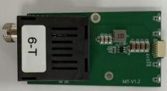
Indicator | Function Description |
P | Power indicator; stays on when power is connected |
F | Fiber indicator; flashes when power is connected, stays on when fiber is connected |
V | Video indicator; stays on when video signal is connected |
D | Data indicator; stays on when data is connected |
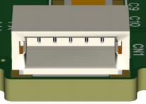
The product uses a 1.0 mm‑pitch data connector (a 30 cm data cable is included).
Pin definitions (left to right):
1.GND
2.VCC 5–24 V
3.VIDEO
4.TX
5.RX (for SBUS protocol, only RX is used)
Parameter | Value |
Operating Voltage | DC-5~9V |
Operating Power | ≤2.1W |
Optical Interface | Single‑fiber FC |
Operating Wavelengths | 1270/1330nm |
Transmission Distance | ≥30KM(optional distances 20/40/60/80/100KM) |
Video Protocol | PAL/NTSC |
Dimensions | 60.5×29×14.5mm |
Weight | 16g |
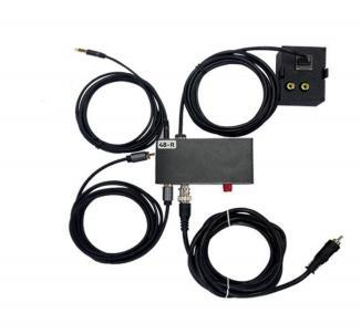
Ground Unit Parameters
Parameter | Value |
Operating Voltage | 2S~6S / XT60 connector |
Operating Power | ≤2.1W |
Optical Interface | Single‑fiber FC |
Operating Wavelengths | 1270/1330nm |
Transmission Distance | ≥30KM |
Video Protocol | PAL/NTSC |
Dimensions | 95mm×62mm×48mm |
Weight | 112g |
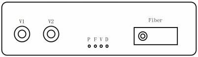
Ground Unit – Front Panel Description
Connector / Indicator | Function |
V1/V2 | 2 video outputs, BNC or RCA (AV) optional |
P | Power indicator |
F | Fiber indicator |
V | Video indicator |
D | Data indicator |
Fiber | FC fiber optic connector |
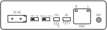
Ground Unit – Rear Panel Description
接口 / 开关 | 功能 |
XT60 | Power input, supports 2S–6S |
Slide Switch 1 | Protocol selection: CRSF / DSC‑PPM |
Slide Switch 2 | Wired / Wireless mode selection |
VTX | Video transmission interface |
RX | Wireless receiver interface |
DSC | Trainer mode (DSC) interface |
CRSF | CRSF protocol interface |
Operating Mode Descriptions
1. Wireless Mode
Set Slide Switch 2 to Wireless. The M/L LEDs are off, and Slide Switch 1 is disabled. Connect a wireless receiver via the VTX/RX interfaces for ground‑end wireless control.
2. Wired Mode
Set Slide Switch 2 to Wired. The M LED stays on, and the L LED flashes. After inserting the corresponding interface, the L LED stays on when the protocol link is established.
3. CRSF Mode
Set Slide Switch 1 to CRSF. Use the corresponding remote‑control adapter board and connect the ground unit to the remote via an Ethernet cable. Set the remote to external module CRSF. The L LED stays on when the link is normal.
4. DSC‑PPM Trainer Mode
Set Slide Switch 1 to Trainer. Use a 3.5 mm audio cable to connect the ground unit’s DSC port to the remote’s DSC port. Turn off the remote’s internal/external RF module and set it to Slave/Jack. The L LED stays on when the link is normal.
5. SBUS Protocol Mode
When using SBUS, set Slide Switch 2 to Wireless and do not connect any other device to the RX terminal. Select SBUS protocol on the remote, insert the adapter board into the remote, and control via SBUS.
Precautions for Use
1. Clean the fiber connector end face before use.
2. Insert the extension rod before use.
3. Secure the mounting bracket before use.
4. Maintain a steady flight speed during operation; avoid rapid descent.
5. Avoid excessive bending, pulling, or squeezing of the fiber during connection.
6. Confirm all connections are correct before applying power.
7. Observe the P, F, V, and D LED indicators during operation to verify that power, fiber, video, and data connections are normal.
--
Request for Quotation
We will reply to all your information about the product in time.
 10+
10 Years of Experience
10+
10 Years of Experience
 50
50 + Countries Bussiness
50
50 + Countries Bussiness
 10000
10k + Diodes sold worldwide
10000
10k + Diodes sold worldwide
 30
30+ Invention patent
30
30+ Invention patent
 10
10+ Advanced Optical Solutions
10
10+ Advanced Optical Solutions
⇪