- Cart
- |
- Personal Center
- |
info@idealphotonics.com


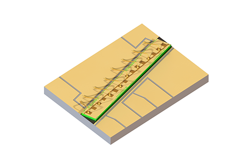
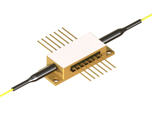
1300nm Booster Optical Amplifier on Submount
A high-power boost optical amplifier (BOA) with a center wavelength of 1300nm and packaged in a chip on carrier (CoC). This product belongs to the MP series carrier integrated optical amplifier, designed specifically for application scenarios that require high gain, low noise, and compact integration.
Product features:High-gain and low-noise amplification; compact submount integration; wide operating wavelength range; intelligent power control; extreme environmental adaptability
Part Number:MP-BOA-1300-150-60-CoC
Application area:Submarine cable relay; space laser communication; military optoelectronic systems; fiber sensing networks; free-space optical communication
Add to Cart Request for Quotation Consult Favorite
Central Wavelength Saturation Output Power Bandwidth
1300nm 22dBm 60nm
Detailed Specifications
Recommended Operating Conditions
@ CW, device mounted on a copper heat sink
Parameter | Min. | Typ. | Max. | Unit |
Heat Sink Temperature | 20 | 25 | 30 | °C |
Forward Current | — | 2000 | 3000 | mA |
Output Power (Amplification Mode) | — | — | 450 | mW |
Input Optical Power* | -20 | 10 | 15 | dBm |
* Fiber-to-chip coupling efficiency taken into account.
Gain Characteristics
@ CW, 25°C, 2000 mA, Input Signal: 10 dBm, 1300 nm(筱晓Id3401 标黄部分改成1300)
Parameter | Min. | Typ. | Max. | Unit |
Forward Current @ 450 mW | — | — | 3000 | mA |
Saturated Output Power @ -3 dB | 18 | 22 | — | dBm |
Gain | 13 | 17 | — | dB |
Small-Signal Gain @ -20 dBm | 25 | 31 | — | dB |
Peak Wavelength | 1290 | 1300 | 1310 | nm |
Bandwidth @ -3 dB | — | 60 | — | nm |
Noise Figure @ Pin = -20 dBm (Excluding input coupling) | — | — | 5 | dB |
ASE Characteristics
@ CW, 25°C, 2000 mA, No Input Signal
Parameter | Min. | Typ. | Max. | Unit |
Output Power (Per Port) | — | 45 | — | mW |
Forward Voltage | — | 1.4 | 2 | V |
Average Wavelength | — | 1202 | — | nm |
Bandwidth (FWHM) | — | 17 | — | nm |
Ripple (RMS)** | — | 0.05 | 1 | dB |
Slow-Axis Beam Divergence (FWHM) | 2 | 6 | 10 | deg |
Fast-Axis Beam Divergence (FWHM) | 22 | 27 | 33 | deg |
Polarization Extinction Ratio (PER) | 14 | 18 | — | dB |
Polarization | — | TE | — | — |
** Measured within 1 nm range near the spectral maximum at 20 pm resolution.
Absolute Maximum Ratings
Parameter | Min. | Max. | Unit |
Output Optical Power | — | 1300 | mW |
Input Optical Power | — | 20 | dBm |
Forward Current | — | 4000 | mA |
Reverse Voltage | — | 2 | V |
Soldering Temperature (Max. 5 s) | — | 250 | °C |
Chip Operating Temperature (Above Dew Point) | 5 | 50 | °C |
Storage Temperature | 5 | 50 | °C |
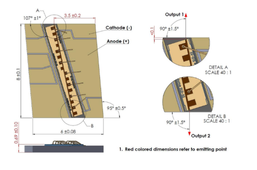
Chip Parameters
Parameter | Min. | Typ. | Max. | Unit |
Chip Length | — | 8 | — | mm |
Front Facet Back Reflection | — | — | 0.001 | % |
Rear Facet Back Reflection | — | — | 0.001 | % |
Model Description
Characteristic Curves
Typical Performance (For Reference Only)
Output Power and Operating Current

Gain Spectrum

Gain and Output Power

Output Power vs. Input Power

Amplified Spectrum

ASE Spectrum

Operating Instructions
Safety and Operating Instructions
The light emitted by this device is invisible and hazardous to human eyes. Avoid direct viewing of the fiber connector while the device is in operation. When operating with the connector uncovered, appropriate laser safety goggles must be worn.
Absolute maximum ratings shall only be applied to the device for a short duration. Long-term exposure to maximum ratings or simultaneous exposure to multiple maximum ratings may cause device damage or reliability degradation. Operation beyond the device’s maximum ratings may result in equipment failure and potential safety hazards. A dedicated matched power supply must be adopted to ensure the maximum forward current is not exceeded.
Devices mounted on heat spreaders require a qualified heat sink. The device shall be fixed to the heat sink with 4 screws (fastened in a cross pattern with an initial torque of 0.075 N·m and a final torque of 0.15 N·m) or clamps. The flatness deviation of the heat sink surface shall be less than 0.05 mm. Indium foil or flexible thermal interface materials are recommended between the device base and the heat sink. Thermal grease is not recommended for this application.
Prevent optical back-reflection, which may degrade the device’s spectral performance and output power stability, and even cause catastrophic facet damage. An optical isolator is strongly recommended to suppress back-reflection.
Do not pull the optical fiber. Avoid bending the fiber with a bending radius less than 3 cm. The fiber end-face shall be fully protected against contamination and mechanical damage during installation. After removing the dust cap, clean the fiber end-face unidirectionally with lens cleaning wipes or cotton swabs moistened with isopropyl alcohol or ethanol. Operate the device only with clean optical fiber connectors.
ESD Protection
Electrostatic discharge is a primary cause of unexpected product failure. Strict ESD precautions must be implemented at all times. Maintain continuous ESD protection during installation, including the use of anti-static wristbands, grounded work surfaces, and standardized anti-static operating procedures.
--
Request for Quotation
We will reply to all your information about the product in time.
⇪