- Cart
- |
- Personal Center
- |
info@idealphotonics.com


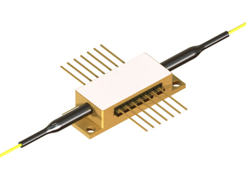
1310nm 24dBm BOA Fiber-Coupled Booster Semiconductor Optical Amplifier
Semiconductor Optical Amplifier (SOA) / Booster Optical Amplifier (BOA)Booster Optical Amplifiers (BOA) are amplifiers that employ semiconductors as the gain medium. They feature a structure similar to Fabry-Pérot laser diodes, with anti-reflection design structures on the end facets. Modern designs adopt anti-reflection coatings, tilted waveguides and window regions, which can reduce facet reflectivity to below 0.001%. This results in higher cavity power loss than gain, preventing the amplifier from lasing.
Product features:Fiber-coupled design; high output power; low-noise amplification; wide wavelength optimization; stable and reliable
Part Number:MP-BOA-1310-200-50-XA
Application area:Fiber Communication | LiDAR | Sensing Network | Medical Laser | Industrial Processing
Add to Cart Request for Quotation Consult Favorite
Central Wavelength Peak Output Power@-3dB Bandwidth @ -3dB
1310nm 24dBm 50nm
Detailed Specifications
Recommended Operating Conditions
Parameter | Min. | Typ. | Max. | Unit |
Operating Current | — | 1000 | 1500 | mA |
Forward Voltage | — | 1.6 | 1.8 | V |
Thermistor Temperature | 20 | 25 | 35 | °C |
Gain Characteristics
@ CW, recommended operating point
Parameter | Min. | Typ. | Max. | Unit |
Output Power ¹·² | 200 | 250 | — | mW |
Average Wavelength ² | 1290 | 1305 | 1320 | nm |
Bandwidth ² @ Ppeak/PASE>95% (ref. graph 1) | — | 50 | — | nm |
Small-Signal Gain ¹·³ | 36 | 39 | — | dB |
Saturated Output Power ¹ @ −3 dB | 18 | 21 | — | dBm |
¹ At maximum gain wavelength² At input signal of +10 dBm³ At input signal of −25 dBm
Amplified Spontaneous Emission (ASE) Characteristics
Each device tested @ CW, recommended operating point, no optical input
Parameter | Min. | Typ. | Max. | Unit |
Optical Power per Port (Fiber-coupled) | — | 60 | — | mW |
Average Wavelength | — | 1300 | — | nm |
Bandwidth ² @ −3 dB | — | 17 | — | nm |
Spectral Ripple ² (RMS within 1 nm span, 10 pm resolution) | — | 0.1 | 0.3 | dB |
Polarization Extinction Ratio (PER) per Port | 15 | 18 | — | dB |
ASE Rise Time | — | 0.5 | — | ns |
ASE Fall Time | — | 0.5 | — | ns |
Absolute Maximum Ratings
Parameter | Min. | Max. | Unit |
BOA Reverse Voltage | — | 2 | V |
BOA CW Forward Current | — | 600 | mA |
Input Optical Power | — | 20 | dBm |
TEC Current | — | 3 | A |
TEC Voltage | — | 4 | V |
Fiber Bending Radius | 3 | — | cm |
Chip Operating Temperature Range | 10 | 40 | °C |
Housing Operating Temperature Range | 0 | 70 | °C |
Storage Temperature Range | -40 | 85 | °C |
Thermistor Specifications | Fiber Specifications | |||||
Parameter | Value | Unit | Parameter | PM980 | HI1060 | Unit |
Thermistor Type | NTC | — | Numerical Aperture, typical | 0.12 | 0.14 | — |
Resistance @ 25 °C | 10 ± 0.1 | kΩ | Cutoff Wavelength | 900 ± 70 | 920 ±50 | Nm |
Beta (25–85 °C) | 3434 ± 1% | K | Mode Field Diameter (@ 1060 nm) | 6.6 ± 0.3 | 6.2 ± 0.3 | μm |
| Cladding Diameter | 125±1 | 125±1 | μm | ||
Coating Diameter | 245±15 | 245±15 | μm | |||
Loose Tube Diameter (Optional) | 900 | 900 | μm | |||
Connector | FC/APC (narrow key) | |||||
Connector Alignment aligned with PANDA fiber | ||||||
Output light is polarized along the slow axis of the PM fiber. | ||||||
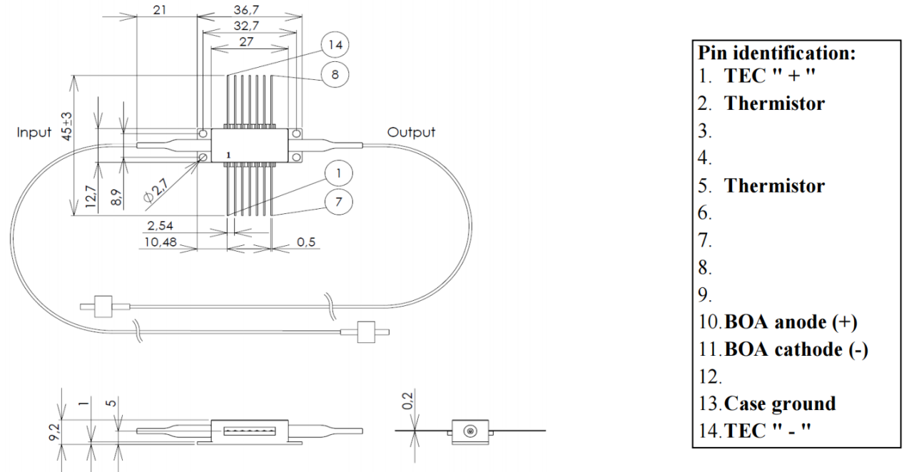
General Specifications
Fiber-Coupled Booster Semiconductor Optical Amplifier – BOA
Part Number | Average Gain Wavelength(nm) | Gain Bandwidth FWHM¹(nm) | Output Power¹(mW) | Saturated Output Power²(dBm) | ASE Ripple RMS³(dB) | Polarization Extinction Ratio PER(dB) | Operating Current(mA) |
MP-BOA-1060-120-80-YY | 1060 | 80 | 120 | 20 | 0.01 | 20 | 400 |
MP-BOA-1310-250-50-YY | 1305 | 50 | 250 | 21 | 0.1 | 18 | 1000 |
Typical Parameters of Fiber-Coupled Semiconductor Optical Amplifier (SOA)
Part Number | Average Gain Wavelength(nm) | Gain Bandwidth FWHM¹(nm) | Small-Signal Gain¹(dB) | Saturated Output Power²(dBm) | Noise Figure(dB) | Peak Gain Wavelength(nm) | Gain Spectrum Tilt(dB) | ASE Power(mW) | ASE Ripple RMS³(dB) | PER(dB) | Operating Current(mA) |
MP-SOA-780-20-YY-30dB | 775 | 20 | 32 | 15 | 6.5 | 775 | – | 7 | 0.03 | 14 | 300 |
MP-SOA-1000-100-YY-30dB | 1000 | 100 | 33 | 18 | 6.5 | 960, 1030 | 1 | 25 | 0.02 | 20 | 600 |
MP-SOA-1020-110-YY-27dB | 1020 | 110 | 27 | 15 | 7.5 | 970, 1040 | 4 | 15 | 0.02 | 20 | 450 |
MP-SOA-1030-20-YY-40dB | 1030 | 20 | 40 | 18 | 8 | 1030 | – | 70 | 0.03 | 20 | 400 |
MP-SOA-1060-20-YY-40dB | 1060 | 22 | 40 | 18 | 8 | 1065 | – | 60 | 0.02 | 20 | 400 |
MP-SOA-1060-90-YY-30dB | 1060 | 90 | 30 | 18 | 5 | 1060 | – | 7 | 0.02 | 20 | 400 |
MP-SOA-1080-20-YY-40dB | 1080 | 27 | 38 | 17 | 7 | 1085 | – | 40 | 0.02 | 20 | 400 |
MP-SOA-1130-20-YY-35dB | 1125 | 25 | 35 | 15 | 10 | 1125 | – | 30 | 0.03 | 20 | 600 |
MP-SOA-1140-90-YY-24dB | 1140 | 90 | 24 | 17 | 4.5 | 1110, 1170 | 5 | 1 | 0.01 | 20 | 400 |
MP-SOA-1190-90-YY-20dB | 1190 | 90 | 20 | 15 | 6.5 | 1160, 1225 | 5 | 0.7 | 0.02 | 20 | 300 |
MP-SOA-1250-110-YY-27dB | 1250 | 110 | 27 | 15 | 7.5 | 1210, 1280 | 6 | 5 | 0.05 | 20 | 900 |
MP-SOA-1290-40-YY-25dB | 1285 | 45 | 24 | 12 | 7.5 | 1290 | – | 1 | 0.02 | 20 | 400 |
¹ @ −25 dBm input signal, at peak gain² @ −3 dB compression, at peak gain³ Measured at ASE peak, RMS within 1 nm span, 10 pm resolution
Characteristic Curves
Typical performance (for reference only)@ CW, chip temperature 25 °C, housing mounted on room-temperature heat sink.
Power spectra at different currents

Gain vs. Output power

Output power at different input signals

Spectra of amplified optical signal

ASE l-I-V characteristics

ASE spectra

Safety and Operating Guidelines
The light emitted by this device is invisible and may be harmful to human eyes. Avoid direct viewing of the fiber connector during device operation. Appropriate laser safety goggles must be worn when operating with the connector uncovered.
The absolute maximum ratings apply to the BOA only for short-term operation. Long-term operation under maximum ratings, or simultaneous exposure to multiple maximum ratings, may cause device damage and degrade reliability. Operating the BOA beyond the maximum ratings may result in device failure and potential safety hazards. The matched power supply for the component must be used to ensure the maximum forward current is not exceeded.
The BOA mounted on a heat spreader requires a proper heat sink. The BOA shall be fixed to the heat sink with four screws (fastened in a cross pattern with an initial torque of 0.075 N·m and a final torque of 0.15 N·m) or clamps. The flatness deviation of the heat sink surface shall be less than 0.05 mm. Indium foil or flexible thermal interface materials are recommended between the device base and the heat sink. Thermal grease is not recommended for this application.
Do not pull the optical fiber. Do not bend the fiber with a bending radius less than 3 cm. Always use clean fiber connectors when operating the BOA. Inspect and clean the connectors regularly if necessary. For cleaning, use cleanroom-compatible wipes dampened with isopropyl alcohol to carefully clean the connector end-face, or use professional fiber cleaning tools. Turn off the BOA driving current before cleaning.
Electrostatic discharge (ESD) may cause permanent device failure. Necessary anti-static protection measures must be taken at all times.
--
Request for Quotation
We will reply to all your information about the product in time.
⇪