- Cart
- |
- Personal Center
- |
info@idealphotonics.com


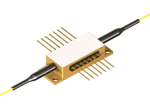
780nm 32dB High-Gain Semiconductor Optical Amplifier
Semiconductor optical amplifiers (SOAs), including booster optical amplifiers (BOAs), are amplifiers that use semiconductors as the gain medium. They have a structure similar to Fabry-Pérot laser diodes but incorporate anti-reflection design elements at their facets. Recent designs feature anti-reflection coatings, tilted waveguides, and window regions, which can reduce facet reflections to below 0.001%. Since this causes the power loss in the cavity to exceed the gain, it prevents the amplifier from functioning as a laser.
Product features:Ultra-high gain; Low polarization sensitivity; Wide bandwidth; Low power consumption; Industrial-grade reliability
Part Number:MP-SOA-780-32db-20-PA
Application area:Ultrafast laser amplification | LiDAR | Biomedical imaging | Industrial processing | Space communications
Add to Cart Request for Quotation Consult Favorite
Center wavelength Output power
775nm 15dBm
Detailed parameters
Specifications:
Test Instructions: Continuous operation, chip temperature 25°C, shell installed on room temperature heat sink
Parameters | Min. value | Typical values | Max. value | unit |
Operating current (IOP). | 300 | 400 | mA | |
Forward voltage @ IOP | 1.9 | 2.1 | V | |
gain | ||||
Small signal gain¹ ² | 28 | 32 | dB | |
Gain average wavelength¹ | 770 | 775 | 790 | nm |
Gain bandwidth¹ @ -3dB | 15 | 20 | nm | |
Gain saturation output power² @ -3dB | 12 | 15 | dBm | |
Noise figure³ *** | 6.5 | dB | ||
Amplify spontaneous radiation | ||||
ASE optical power per port | 5 | 7 | mW | |
ASE average wavelength | 770 | 775 | 790 | nm |
ASE bandwidth @ -3dB | 12 | 15 | nm | |
ASE** spectral ripple³ (RMS in the 1nm range, 10pm resolution) | 0.03 | 0.2 | dB | |
ASE rise time | 0.15 | ns | ||
ASE decline time | 0.5 | ns | ||
Polarization extinction ratio (PER) per ASE port | 10 | 14 | dB | |
1. The input optical power is -25dBm
* No input light
2. In the gain Max. wavelength
** Output ports
3. In ASEMax. It is at the wavelength
*** 2 NF = 10 log10(ρASE / Ghν)(D。 Baney et al., Fiber Optic Technology 6, 122 (2000)]
Typical SOA parameters and operating current Test conditions: continuous operation, input signal 25dBm, chip temperature 25°C, chassis temperature 25°C | ||||
Operating current, mA | Gain, dB | Gain bandwidth @ -3dB, nm | Saturated output power @ -3dB, dBm | Ripple RMS, dB |
200 | 23 | 22 | 14 | 0.02 |
300 | 31 | 20 | 15 | 0.03 |
400 | 35 | 17 | 17 | 0.04 |
Absolute Max. Rated parameters | |||
Parameters | Min. value | Max. value | unit |
SOA reverse voltage | - | 2 | V |
SOA CW forward current | - | 400 | mA |
Input optical power | - | 10 | dBm |
thermoelectric cooler current | - | 3 | A |
Thermoelectric cooler voltage | - | 4 | V |
Fiber bending radius | 3 | - | cm |
Chip operating temperature range | 10 | 40 | °C |
Enclosure operating temperature range | 0 | 70 | °C |
Storage temperature range | -40 | 85 | °C |
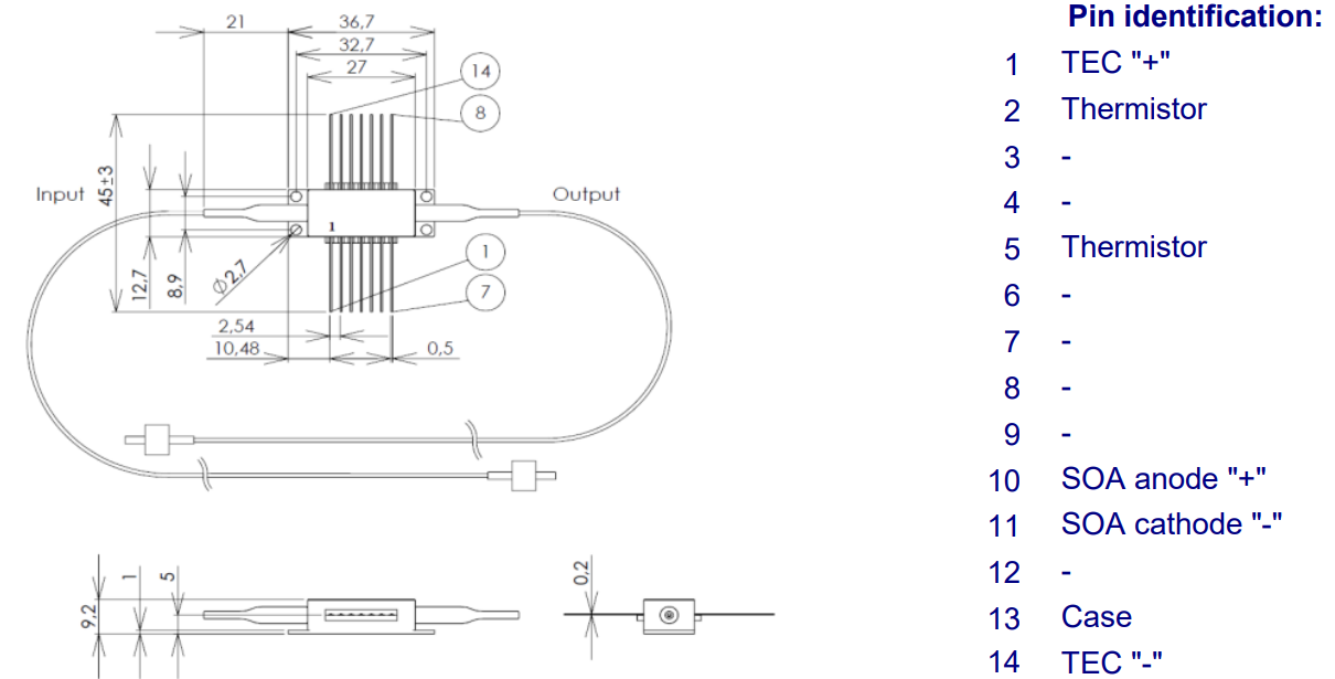
Thermistor specifications | Fiber Specifications | |||||
Parameters | Numerical values | unit | Parameters | HI780 | PM780 | unit |
Type | NTC | - | NA typical | 0.14 | 0.12 | |
Resistance @25°C | 10 ± 0.1 | kOhm | Cut-off wavelength | 720±50 | 710±60 | nm |
Beta 25-85°C | 3435±1% | K | The diameter of the mold field is @780nm | 4.6±0.5 | 4.6±1.0 | μm |
| Cladding diameter | 125±1 | 125±1 | μm | ||
Coating diameter | 245±15 | 245±15 | μm | |||
Loose Tube Diameter(optional) | 900 | um | ||||
interface | FC/APC(narrow key) | |||||
Connector alignment Panda type fiber:
The output light is polarized along the slow axis of the PM fiber.
| ||||||
General parameters
Fiber Optic Coupling Boost Semiconductor Optical Amplifier-BOA (New).
Part number | Gain average wavelength | Gain bandwidth FWHM 1 | Output power 1 | Saturation output power 2 | ASE ripple RMS 3 | Polarization extinction ratio PER | Operating current |
nm | nm | mW | dBm | dB | dB | mA | |
1060 | 80 | 120 | 20 | 0.01 | 20 | 400 | |
1305 | 50 | 250 | 21 | 0.1 | 18 | 1000 |
Typical parameters of fiber-coupled semiconductor optical amplifiers (SOAs).
Part number | Gain average wavelength | Gain bandwidth FWHM 1 | Small signal gain 1 | Saturation output power 2 | Noise figure | Gain Max. wavelength | Gain spectrum decreases | ASE power | ASE ripple RMS 3 | Polarization extinction ratio PER | Operating current |
nm | nm | dB | dBm | dB | nm | dB | mW | dB | dB | mA | |
775 | 20 | 32 | 15 | 6.5 | 775 | – | 7 | 0.03 | 14 | 300 | |
1000 | 100 | 33 | 18 | 6.5 | 960, 1030 | 1 | 25 | 002 | 20 | 600 | |
1020 | 110 | 27 | 15 | 7.5 | 970, 1040 | 4 | 15 | 0.02 | 20 | 450 | |
1030 | 20 | 40 | 18 | 8 | 1030 | – | 70 | 0.03 | 20 | 400 | |
1060 | 22 | 40 | 18 | 8 | 1065 | – | 60 | 0.02 | 20 | 400 | |
1060 | 90 | 30 | 18 | 5 | 1060 | – | 7 | 0.02 | 20 | 400 | |
1080 | 27 | 38 | 17 | 7 | 1085 | – | 40 | 0.02 | 20 | 400 | |
1125 | 25 | 35 | 15 | 10 | 1125 | – | 30 | 0.03 | 20 | 600 | |
1140 | 90 | 24 | 17 | 4.5 | 1110, 1170 | 5 | 1 | 0.01 | 20 | 400 | |
1190 | 90 | 20 | 15 | 6.5 | 1160, 1225 | 5 | 0.7 | 0.02 | 20 | 300 | |
1250 | 110 | 27 | 15 | 7.5 | 1210 , 1280 | 6 | 5 | 0.05 | 20 | 900 | |
1285 | 45 | 24 | 12 | 7.5 | 1290 | – | 1 | 0.02 | 20 | 400 |
1 – @ – 25dBm input signal, Max. Gain2
2– @ – 3dB, Max. Gain3
3– @ASE Max. value, RMS in the 1 nm range, 10pm resolution
Characteristic curves
Typical performance
For reference only, test conditions: continuous operation, chip temperature 25°C, shell installed on room temperature heat sink
Gain Spectra at different currents

Gain and Output power vs. Input signal

Gain spectra at different input signals

Spectra of amplifed optical signal

ASE Spectra(no input signal)

Output power at differnet input signals

1. Absorption of line-polarized 100uW broadband SLD radiation (SOA short circuit). Measured after the SOA output port polarizer.
2. Absorption of line-polarized single-frequency laser radiation (SOA short circuit). Measured after the SOA output port polarizer.
Operating instructions
Safety and Operational Guidelines
The light emitted by such devices is invisible and can be harmful to the human eye. When operating the device, avoid looking directly at the fiber optic connector. Appropriate laser safety glasses must be worn during operation and the connector must be opened.
jue's high rating on z only applies to BOA in the short term. Prolonged exposure to Max. rated or exposed to multiple Max. Rated values may cause damage to the device or affect the reliability of the equipment. More than Max. Rated operation of BOA may lead to equipment failure or safety hazards. The power supply used by the component must be ensured that it does not exceed Max. Forward current.
BOA on the heatsink requires a suitable heat sink. The BOA must be mounted on the radiator with 4 screws (the bolts are fixed in an x-shaped way, the initial torque is set to 0.075Nm, and the final x-bolt is set at 0. 15Nm) or clamps. The surface flatness deviation of the radiator is less than 0.05mm. Indium foil or thermally conductive soft material is recommended for the thermal interface between the bottom of the case and the heatsink. It is undesirable to use thermal grease.
Do not pull the fiber. Do not bend the fiber with a bending radius of less than 3cm. When operating BOA, use clean fiber optic connectors. Regularly inspect and clean the connectors if necessary. To clean the connector, simply use a cleanroom-compatible paper towel, apply some isopropyl alcohol, carefully clean the small side of the connector, or use a dedicated fiber cleaning tool. When cleaning, turn off the BOA current.
Electrostatic discharge can cause equipment failure. Take necessary anti-static measures.
--
Request for Quotation
We will reply to all your information about the product in time.
⇪