- Cart
- |
- Personal Center
- |
info@idealphotonics.com


780nm 30dB High-Gain Semiconductor Optical Amplifier
This is a high-performance semiconductor optical amplifier with a central wavelength of 780nm and a typical small-signal gain of 30dB. The device is specifically designed for applications requiring extremely high gain and moderate bandwidth amplification, making it particularly suitable for quantum optics, optical coherence tomography (OCT), and precision measurement systems related to rubidium atomic absorption lines
Product features:High gain coefficient;Narrowband optimized amplification;Low power consumption operation;Excellent signal-to-noise ratio;Strong temperature stability
Part Number:MP-SOA-780-30db-16-XA
Application area:Precision laser measurement | Quantum optics experiments | Fiber-optic sensing systems | Medical diagnostic equipment | Research-grade optical systems
Add to Cart Request for Quotation Consult Favorite
Center wavelength Output power
780nm 16dBm
Detailed parameters
Recommended operating conditions
@CW, the enclosure is mounted on a room temperature radiator
Parameters | Min. value | Typical values | Max. value | unit |
Chip temperature | 20 | 25 | 30 | ℃ |
Forward current | 300 | 400 | mA | |
Input optical power | -40 | -25 | 10 |
Gain characteristics
@ CW, 25°C, 250mA, -25dBm @ 780nm input signal
Parameters | Min. value | Typical values | Max. value | unit |
Small signal gain at 300mA | 25 | 30 | dB | |
Saturated Output Power at 300mA (-3dB)@300mA | 8 | 11 | dBm | |
Wavelength of Gain Maximum | 770 | 780 | 790 | nm |
Gain bandwidth (FWHM). | 13 | 16 | nm | |
Noise figure* | 6.5 | dB |
- NF = 10log10(2p_ase/ghv) [D.Baney et al., Fiber Optic Technology. 6, 122 (2000)]
Amplified spontaneous radiation (ASE) characteristics
@CW, 25°C, 250mA, no input signal
Parameters | Min. value | Typical values | Max. value | unit |
Output power (per port) | 10 | mW | ||
Forward voltage | 1.9 | 2.2 | V | |
Average wavelength | 770 | 780 | 790 | nm |
Bandwidth (FWHM). | 10 | 13 | nm | |
Ripple** (RMS). | 0.01 | 0.2 | dB | |
Polarization extinction ratio (PER). | 10 | 15 | dB | |
polarization | TE |
** -measured in 1nm span around spectrum maximum with 20pm resolution
Absolute Maximum Ratings
Parameters | Min. value | Max. value | unit |
Output optical power | 150 | mW | |
Input optical power | 10 | dBm | |
Forward current | 400 | mA | |
Reverse voltage | 2 | V | |
TEC current | 3 | A | |
TEC voltage | 4 | V | |
Chip operating temperature | 10 | 40 | °C |
Enclosure operating temperature | 0 | 70 | °C |
Storage temperature | -40 | 85 | °C |
Pin soldering temperature (up to 10 seconds, z-high case temperature 120°C). | 300 | °C | |
Fiber optic band radius | 3 | cm |
Characteristic curves
Typical performance (for reference only)
@CW, the case is mounted on a room temperature heatsink
Gain spectra at different currents

Gain and Output Power vs. Input Signal

Gain spectra at different input signals

Spectra of amplified optical signal

ASE Spectra(no input signal)

Output power at different input signals

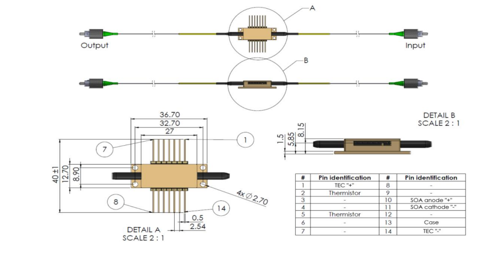
Thermistor specifications | Fiber Specifications | |||||
Parameters | Numerical values | unit | Parameters | HI780 | PM780 | unit |
Type | NTC | - | NA typical | 0.14 | 0.12 | |
Resistance @25°C | 10 ± 0.1 | kOhm | Cut-off wavelength | 720±50 | 710±60 | nm |
Beta 25-85°C | 3435±1% | K | The diameter of the mold field is @780nm | 4.6±0.5 | 4.6±1.0 | μm |
| Cladding diameter | 125±1 | 125±1 | μm | ||
Coating diameter | 245±15 | 245±15 | μm | |||
Loose Tube Diameter(optional) | 900 | um | ||||
interface | FC/APC(narrow key) | |||||
Connector alignment Panda type fiber:
The output light is polarized along the slow axis of the PM fiber.
| ||||||
Operating instructions
Safety and operating instructions
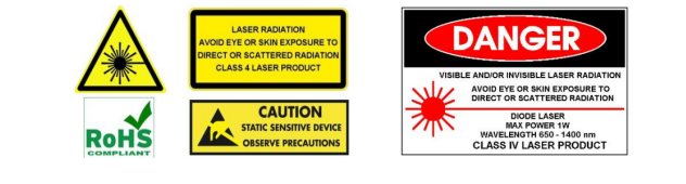
The light emitted by this device is invisible and harmful to the human eye. While the device is running, avoid looking directly at the fiber optic connector. When operating with the connector open, it is essential to wear appropriate laser safety glasses.
jue to Max. The rating can only be applied to the device for a short period of time. Prolonged exposure to Max. Rated or exposed to multiple Max. Ratings may cause damage to the device or affect the reliability of the device. In the Max. Operating equipment outside of its rating may result in equipment failure or safety hazards. The power supply used with the components must be used to enable the Max. The forward current does not exceed.
The equipment on the heat radiator requires a proper heat sink. The unit must be mounted on the radiator using 4 screws (X-bolted with an initial torque set at 0.075Nm and finally an X-bolt with a torque set at 0.15Nm) or a clamp. The flatness deviation of the radiator surface must be less than 0.05mm. It is recommended to use indium foil or a thermally conductive soft material as the thermal interface between the bottom of the housing and the heat sink. It is not advisable to use thermal grease for this.
Avoid device back reflection. It can affect the performance of the device in terms of spectral and power stability.
It can also lead to fatal face damage. A light isolator is highly recommended to block back reflections.
Do not pull the fiber. Do not bend fibers with a radius of less than 3 cm. The top of the fiber should always be protected from any contamination or damage during installation. After removing the dust cover on the top of the fiber, carefully clean the top of the fiber using an optical lens cleaning paper or cotton swab stained with isopropyl alcohol or ethanol in one direction. Operate the device only with clean fiber optic connectors.
ESD Protection - Electrostatic discharge is the leading cause of unexpected product failure. Take extreme precautions to prevent ESD. ESD protection must be maintained during equipment installation – using wrist straps, grounded work surfaces, and strict anti-static technology when handling products.
--
Request for Quotation
We will reply to all your information about the product in time.
⇪