- Cart
- |
- Personal Center
- |
info@idealphotonics.com


1310nm 400mW SM DFB Laser Diode
Distributed feedback (DFB) and distributed Bragg reflector (DBR) laser diodes are light sources emitting an extremely narrow spectral line with a bandwidth below 5 MHz and typical side mode suppression ratio (SMSR) > 40 dB.GaAs-based DFB and DBR lasers utilize InGaAs quantum well (QW) or InAs/GaAs quantum dot (QD) active regions and proprietary chip designs, covering the spectral range from 970 nm to 1330 nm.To date, DFB and DBR lasers are common laser variants, especially for use in scientific research and operations.Both laser types operate in a single longitudinal mode and are highly reliable in terms of efficiency, spectral purity, and long-term performance across various applications.
Product features:High stability output; single longitudinal mode narrow linewidth; wavelength stability; low noise performance; compact modular design
Part Number:MP-DFB-1310-400-A81-14BF-SA
Application area:Coherent Optical Communication | Fiber Optic Sensing | Precision Measurement | Quantum Optics | Scientific Research Instruments
Add to Cart Request for Quotation Consult Favorite
Central Wavelength Output Power
1310nm 400mW
Specifications
Recommended Operating Conditions
@ CW, Module mounted on heat sink at room temperature
Parameter | Min. | Typ. | Max. | Unit |
Chip Temperature | 20 | 25* | 40 | ℃ |
Forward Current | — | 1500 | 1850 | mA |
Output Power** | 350 | — | 450 | mW |
*May vary depending on selected wavelength in some cases
**No kinking over full operating range
Characteristics
@ CW, 25℃*, 800 mA
Parameter | Min. | Typ. | Max. | Unit |
Output Power @ 1800 mA | 400 | — | — | mW |
Forward Voltage | — | 2.6 | 3.5 | V |
Threshold Current | — | 60 | 100 | mA |
Peak Wavelength** (customer selectable) | 1300 | — | 1330 | nm |
Peak Wavelength Tolerance | — | — | ±1 | nm |
Wavelength Tuning vs. Temperature | — | 120 | — | pm/℃ |
Wavelength Tuning vs. Current | — | 4 | — | pm/mA |
Side Mode Suppression Ratio (SMSR) | 40 | 50 | — | dB |
*Temperature may vary from 20 to 40℃ depending on selected wavelength in some cases**Achievable within wavelength tolerance at power > 100 mW
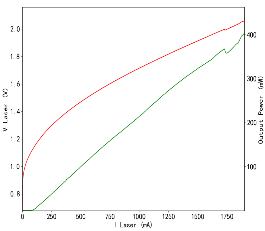
Typical Performance (For Reference Only)
L-I-V Curves
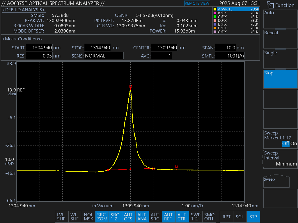
Optical Spectrum
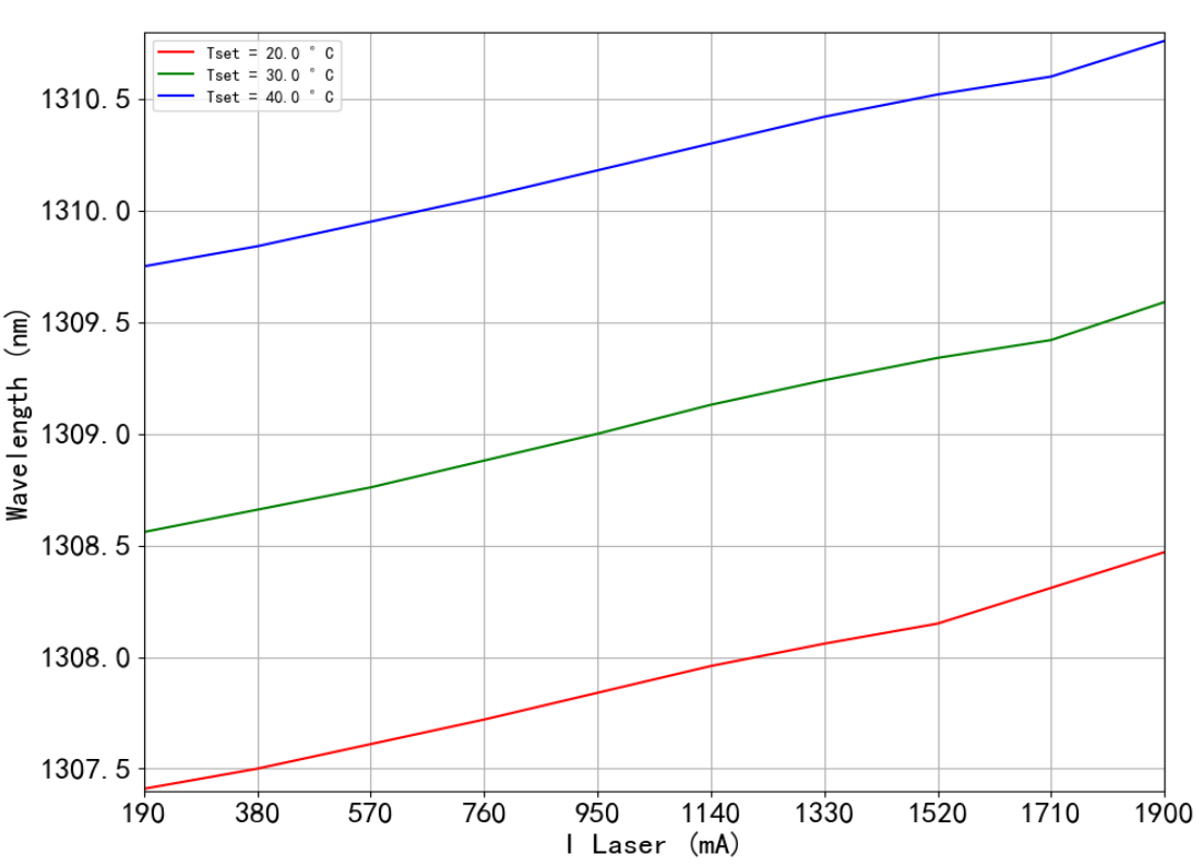
Wavelength Tunability
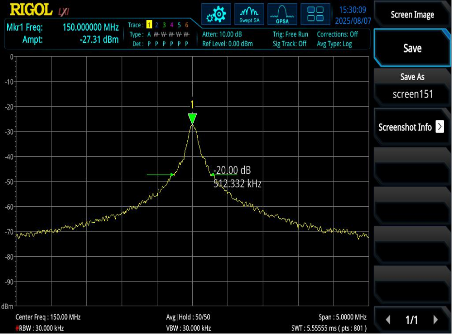
Linewidth(CW, 25.617kHz@25deg, 500mA)
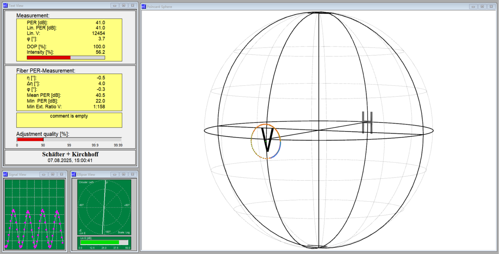
Polarization Test
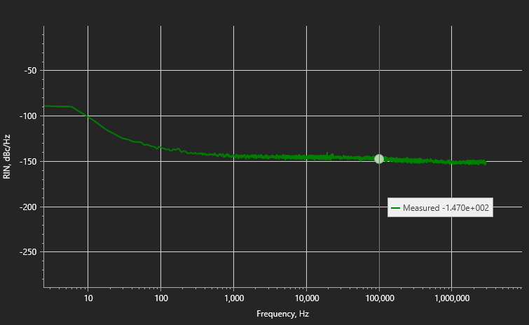
RIN
The above experimental data are tested and provided by the Advanced Optics Laboratory.
Parameter | Min | Max | Unit |
Forward Current | — | 2000 | mA |
Reverse Voltage | — | 2 | V |
TEC Current | — | 3 | A |
TEC Voltage | — | 4 | V |
Chip Operating Temperature | 5 | 50 | ℃ |
Case Operating Temperature | 0 | 70 | ℃ |
Storage Temperature | -40 | 85 | ℃ |
Fiber Bend Radius | 3 | — | cm |
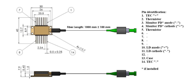
General Parameters
Thermistor Specifications | Fiber Specifications | |||||
Parameter | Value | Unit | Parameter | PM1300 | HI1060 | Unit |
Thermistor Type | NTC | — | Numerical Aperture, typical | 0.12 | 0.14 | — |
Resistance @ 25 °C | 10 ± 0.1 | kΩ | Cutoff Wavelength | 1200 ± 70 | 920 ±50 | Nm |
Beta (25–85 °C) | 3375 ± 1% | K | Mode Field Diameter | 9.3 ± 0.5@1300nm | 6.2 ± 0.3@ 1060 nm | μm |
| Cladding Diameter | 125±1 | 125±1 | μm | ||
Coating Diameter | 245±15 | 245±15 | μm | |||
Loose Tube Diameter (Optional) | 900 | 900 | μm | |||
Connector | FC/APC (narrow key) | |||||
Connector Alignment aligned with PANDA fiber | ||||||
Output light is polarized along the slow axis of the PM fiber. | ||||||
Typical Parameters of Fiber-Coupled DFB Laser Modules
Part Number | Integrated Optical Isolator¹ | Peak Wavelength Range² | Output Power | Operating Current | Threshold Current | SMSR | Wavelength Tuning vs. Temp | Wavelength Tuning vs. Current | PER |
nm | mW | mA | mA | dB | pm/K | pm/mA | dB | ||
MP-DFB-9XX-YY-30 | No | 968 – 986 | 30 | 100 | 20 | 55 | 90 | 1.5 | 18 |
MP-DFB-10XX-YY-50 | No | 1020 – 1120 | 50 | 200 | 30 | 55 | 100 | 2 | 18 |
MP-DFB-10XX-YY-30-VO (New) | Yes | 1020 – 1120 | 30 | 200 | 30 | 55 | 100 | 2 | 18 |
MP-DFB-11XX-YY-50 | No | 1120 – 1200 | 50 | 300 | 30 | 50 | 110 | 2 | 18 |
MP-DFB-11XX-YY-30-VO (New) | Yes | 1120 – 1200 | 30 | 300 | 30 | 50 | 110 | 2 | 18 |
MP-DFB-12XX-YY-50 | No | 1200 – 1280 | 50 | 350 | 50 | 50 | 120 | 2 | 18 |
MP-DFB-12XX-YY-60-VO (New) | Yes | 1200 – 1280 | 60 | 350 | 50 | 50 | 120 | 2 | 18 |
MP-DFB-13XX-YY-50 | No | 1280 – 1330 | 50 | 350 | 50 | 50 | 120 | 2.5 | 18 |
MP-DFB-13XX-YY-60-VO (New) | Yes | 1280 – 1330 | 60 | 350 | 50 | 50 | 120 | 2.5 | 18 |
MP-DFB-13XX-YY-100-VO (New) | Yes | 1280 – 1330 | 100 | 800 | 60 | 50 | 120 | 4 | 18 |
Notes
1 Free-space optical design
2 Any wavelength within this range is available with ±1 nm tolerance
Safety and Operating Instructions
The device emits invisible light that may be harmful to human eyes. Avoid direct eye exposure to the fiber connector during operation. When operating with the connector open, appropriate laser safety goggles must be worn.
Absolute maximum ratings shall be applied to the device only for short periods. Prolonged exposure to maximum ratings or exposure to more than one maximum rating may damage the device or degrade its reliability. Operation beyond the absolute maximum ratings may result in device failure or safety hazards.
A suitable power supply must be used to ensure the maximum forward current is not exceeded.
The device requires a proper heat sink. It must be mounted using 4 screws (cross-tightened with an initial torque of 0.075 Nm and final torque of 0.15 Nm) or a clamp. Flatness deviation of the heat sink surface must be less than 0.05 mm. Indium foil or soft thermally conductive material is recommended as the thermal interface between the package base and heat sink. Thermal grease is not recommended.
--
Request for Quotation
We will reply to all your information about the product in time.
⇪