- Cart
- |
- Personal Center
- |
info@idealphotonics.com


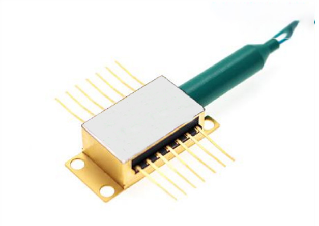
808nm 200mW SM Pumping Laser
Optical output power up to 250mW, 14-pin butterfly package, wavelength locked by fiber Bragg grating, integrated TEC, thermistor, and PD, excellent low power stability.
Product features:Single-mode fiber output; high power stability; narrow linewidth characteristic; low noise design; industrial-grade package
Part Number:MP-FP-808-200-14BF-SA
Application area:Fiber Amplifier Pumping | Fiber Lasers | Coherent Optical Communication | Fiber Optic Sensing | Quantum Technology
Add to Cart Request for Quotation Consult Favorite
Center Wavelength Output Power
808nm 400mW
Model Parameters
Parameter | Symbol | Min | Typ | Max | Unit |
Center Wavelength | λ | 807 | 808 | 809 | nm |
Spectral Width | Δλ | 0.6 | 0.8 | 2.0 | nm |
Threshold Current | Ith | – | 30 | 40 | mA |
Operating Current | Iop | – | 250 | 350 | mA |
Fiber Output Power | Pf | 100 | 200 | 250 | mW |
Wavelength Tuning vs. Temperature | Δλ/T | – | – | 0.01 | nm/°C |
Tracking Ratio (0.1Pop < Pf < Pop)¹ | TR | 0.52 | – | 1.48 | – |
Tracking Error² | TE | −48 | – | +48 | – |
PD Monitor Responsivity | IBF | 0.5 | – | 5 | μA/mW |
PD Dark Current (VRD = 5 V) | Id | – | – | 0.1 | μA |
Extinction Ratio (PM Version) | PER | 17 | 20 | – | dB |
Fiber Type | HI780 | ||||
Forward Voltage | Vf | – | 1.8 | 2.6 | V |
Thermistor Resistance | RT | 9.5 | 10 | 10.5 | kΩ |
Thermistor Temperature Coefficient | – | – | -4.4 | – | %/°C |
Output Connector | – | – | None or FC/APC | – | – |
Note 1:
The tracking ratio is a measure of the tracking between the output power and the monitor photocurrent as the output power varies. On a plot of optical power versus back facet photocurrent, a straight line is drawn between the minimum power (30 mW) and the operating power (Pop). The tracking ratio is defined as the ratio of the measured optical power (as indicated by the data point on the graph) to the value derived from the straight line.
Note 2:
Tracking error is defined as the normalized change in output power relative to Pf at 25°C, i.e., (Pf - Pf-25) / Pf-25, over a case temperature range of 0°C to 75°C, at a constant back facet monitor current corresponding to the lowest back facet monitor current at Pf = Pop at 0°C, 25°C, and 75°C.
Absolute maximum parameter:
Parameters | symbol | unit | Min. | typical | Max. | Test conditions |
Body temperature | TOP | ℃ | -5 | 25 | 70 | |
Chip temperature | TLD | ℃ | +10 | 25 | 50 | |
Operating current | If-max | mA | 0 | 250 | 350 | |
Forward voltage | VR | V | 0.8 | 1.2 | 1.8 | |
TEC current | ITEC | A | - | 1.2 | 2.0 | |
Tec voltage | VTEC | V | - | - | - | |
Axial tension | N | - | - | 5N | 3x10s | |
Lateral pull | N | - | - | 2.5N | 3x10s | |
Fiber bending radius | 16mm | - | ||||
Reverse voltage (LD). | V | - | - | 1.8 | C=100pF,R=1.5KΩ,HBM | |
Reverse voltage (PD). | VPD | V | - | - | 10 | C=100pF,R=1.5KΩ,HBM |
LD electrostatic discharge | VESD-LD | V | - | 1000 | ||
PD electrostatic discharge | VESD-PD | V | - | 500 | ||
PD forward current | IPF | mA | - | 10 | ||
lead soldering time | S | - | 10s | 300℃ | ||
Storage temperature | TSTG | ℃ | -40 | - | +85 | 2000hr |
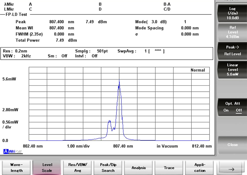
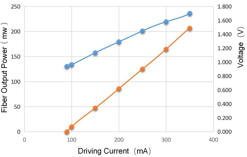
Characteristic curves
Spectrogram:
Output power curve
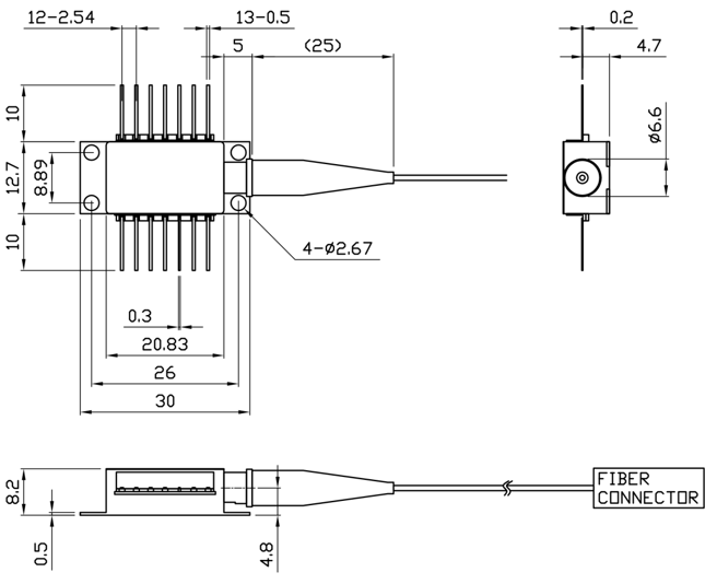
Pin definition
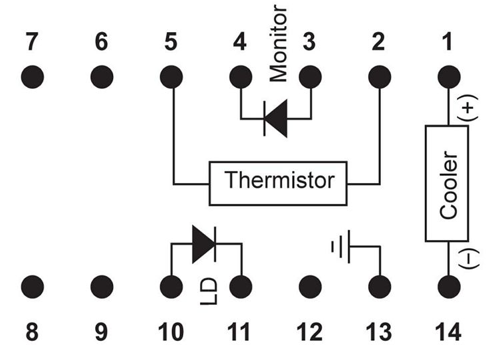
1 | Thermoelectric Cooler (+) | 8 | N/C |
2 | Thermistor | 9 | N/C |
3 | PD Monitor Anode (-) | 10 | Laser Anode (+) |
4 | PD Monitor Cathode (+) | 11 | Laser Cathode (–) |
5 | Thermistor | 12 | N/C |
6 | N/C | 13 | Case Ground |
7 | N/C | 14 | Thermoelectric Cooler (–) |
Ordering information
MP-FP-□□□□-☆-A8▽-XX
□□□□:Wavelength
405: 405nm
633: 633nm
680: 680nm
808: 808nm
850: 850nm
910: 910nm
980: 980nm
*****
1550: 1550nm
☆ :Output Power
A: 100mW
B: 200mW
C: 250mW
▽:Wavelength Tolerance
1:±1nm
2:±2nm
XX: Fiber and Connector Type
SA=HI780+ FC/APC
SP=HI780+ FC/PC
PP=PM 980 + FC/PC
PA=PM980+ FC/APC
--
Request for Quotation
We will reply to all your information about the product in time.
⇪