

ALL CATEGORIES
COMPANY INFO
LINKED


 编辑
编辑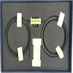
Delivery Fee : $0.00
Quantity :
| Part NO. : | MIOC-13-09-80-N–series |
| Datasheet : |

|
| Availability : |
In store |
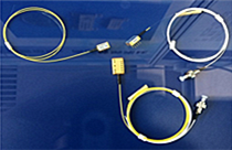
Integrated Optic Chip for Gyroscope (Y waveguide modulators)
Model: IOC-13-09-80-N
1310nm integrated optical chips ( Y waveguide)
input: 125/250um PM fiber
output with 80/165um PM fiber,1m fiber length, without connector
Features
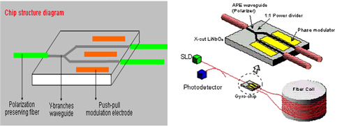
X-Cut, y-propagating LiNbO3
Very low insertion loss.
APE process for waveguide, works in single polarization
High extinction ratio
Fiber is sloping coupled with waveguide, which deduce optical return far and away
Push-pull electrode design may deduce half wave Voltage
Small packaging and lightweight
Excellent long-term stability
Applications
It is for attitude control of movements such as aircrafts, ships, guided missiles, automobiles etc,in the fiber gyroscope system, Hydrophone and other optic sensitive fields. Faraday Effect was used to measure current through fiber circuit in the current sensing system.
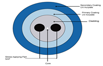
Chip structure
Parameter
Unit
Values
Wavelength
nm
1310
Insertion
dB
≤4.0
Half wave Voltage
V
≤4.0
Splitting Beam Ratio
-
47/53-53/47
Optical Return
dB
≥50
Polarization extinction ,chip
dB
≥55
Additional Intensity Modulating
-
≤0.2%
PM Pigtail Crosstalk
dB
≤-30
Electrode type
-
Push-pull modulating
Bandwidth
MHz
≥300
Pigtail type
-
PM
Work temperature
℃
-40~+70
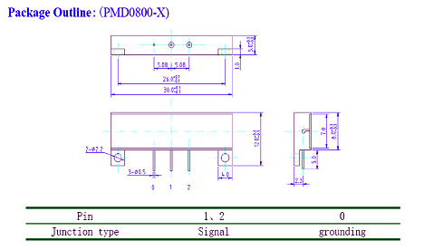
Packaging dimensions
mm
30X8X5 or 35X10X5
Specifications
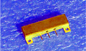
Product photo and outline
Package outline
Operation Instructions
a. If the devices work under the single state of polarization, the polarization state of input light must conform to devices.
b. Avoid the Electrical damage of the devices; the electrode voltage of modulators should be lower 30V.
c. Applying too much force to fiber may cause it broking easily. Avoid drawing、twisting.
Bending radius must not be less than 30nm.
d. Avoid too much force between metal tube and fibers. Put up the tube and the fibers together when using it. Avoid bending at the joint of the tube and the fibers.
e. Storage environment humidity must be less than 50%, and not contain the materials which damages devices.
f. Avoid the devices suffering from intense thermal shock and inhomogeneous by heated
g. Avoid stressing to the joint of the fiber connection circuits.
Related Items
|
High Sensitivity
PIN-FET Receiver Module |
Accelerometer
Family |
Polarization Maintaining Fiber(PMF) |
 |
 |
 |