


ALL CATEGORIES
COMPANY INFO
LINKED


 编辑
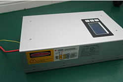
编辑DY20 CO2 Glass Laser Tube Power Supply
Category: Gas Laser
Publish Time: 2014-07-10 21:57
Price : $0.00
Delivery Fee : $0.00
Quantity :
Delivery Fee : $0.00
Quantity :
| Part NO. : | DCFBG-series |
| Datasheet : |

|
| Availability : |
DY20 CO2 Glass Laser Tube Power Supply

I. Instruction for sub-connection wire of the control end
|
1 2 3 4 5 6 5V TH TL WP G IN |
1) Footer 1 is 5V
power supply. (Not needed when connecting the cardinal plate. It is used when
regulating the power with potentiometer, and the 5V current should be less than
10 mA.
3) Footer 5 G refers to ground, and 6 refers to input end.
4) When connecting the control plate, connect the light signal with footer2 in
5) PWM can also be used in footer 6, but the pulse peak is required to reach 5V, and the frequency should be above 20K.
6) For testing: 3, 4 and 5 are in short circuit (or 4, 5 are in short circuit and 3, 5 are connected to switch), the potentiometer center is connected with 6 IN, and the two other ends are connected to 5V and ground (1 and 5) respectively.
7) nected, and 4 and 5 are in water protection.
8) It is not proposed to control laser power with high frequency modulation, because it will have impact on the service life of the laser.
9) The model is applicable to W4 laser, it is necessary to regulate and use the current according to the laser instructions.
II.Instruction for power wire
|
Footer 1 Ground |
footer 2 footer3 AC 220V 50HZ 10A |
Note: The table 10A refers to the connection wire requirement, but not the actual
power dissipation.III. Instruction for laser connection wire
1) The positive red-line with high voltage is connected to the laser tail
2) The negative white-line is connected to laser output window
IV. Current limitation
To limit the working current, the potentiometer (lies in the underside of the power
supply) should be rotated in counterclockwise (please refer to the schematic diagram in our website: www.idealphotonics.com). Limit the maximum output current as it is regulated in the operating instruction. The working current should be limited before delivery.
V. Linear scale between input signal and the output current
Turn around the potentiometer, the linear scale will be changed: for example, when the input signal is 0-5V, the output current is 0-40mA.Or when the input signal is 0-2V, the output signal is 0-40mA.
Note: when the potentiometer is turned down too much, the real output current will be brought down by the same input signal.
VI. Using current
The use standard for our power supply is under 220V, 50Hz. The fluctuation of the input voltage and frequency will affect the working current provided by the power supply,the effection is linear relative. The unstable of the input voltage will affect the output power of the laser tube. The fluctuation of the input voltage has no effection on the lifespan of the laser if only the current provided by the power supply is not over the current limitation.
The ammeter is concatenated to the cathode line.
Related Items
|
10um series of optical fiber |
10um series of optical fiber |
10um series of optical fiber |
 |
|
|